On-vehicle actuator system

a technology of actuators and vehicles, applied in the direction of motor/generator/converter stoppers, electric devices, dynamo-electric converter control, etc., can solve the problems of motor not being able to produce torque, motor not being and the vehicle power supply system may not be able to absorb motor electricity generated by the motor, etc., to minimize the possibility of adverse effects

Inactive Publication Date: 2009-01-29
HITACHI LTD
View PDF7 Cites 16 Cited by
  • Summary
  • Abstract
  • Description
  • Claims
  • Application Information

AI Technical Summary

Benefits of technology

[0004]Motors are generally controlled by driving switching devices with a pulse width modulation. An inverter circuit including a plurality of switching devices is supplied electricity from a vehicle power supply system but, when a motor functions as an electric generator or regenerative device, supplies electricity to the vehicle power system. The vehicle power supply system may be constructed of a DC-DC converter to adjust a motor application voltage, or a diode may be installed between the vehicle power supply system and the inverter circuit to avoid failures caused by a capacitor ground fault in the inverter circuit or by a wrong connection between positive and negative terminals. Where the vehicle power supply system is constructed of a DC-DC converter, or where there is a diode between the vehicle power supply system and the inverter circuit, the vehicle power supply system may not be able to absorb electricity generated by the motor. Further, even if the vehicle power supply system has a battery or capacitor, it may not be able to absorb the electricity produced by the motor because of insufficient storage capacity of the battery and capacitor.
[0025]According to one example of this invention, even when the motor generates or regenerates power, it does not output power to the vehicle power supply system. This makes it possible to construct the system without considering the requirement of the vehicle power supply system being able to absorb power. As a result, even if the motor is rotated by an external force, the torque can be controlled independently of the revolution speed. Even in an operation that frequently switches between high-speed rotation, stop and low-speed rotation, power does not flow from the inverter circuit to the vehicle power supply system, thus minimizing a possibility of adversely affecting the vehicle power supply system and other systems surrounding the on-vehicle actuator system.

Problems solved by technology

Where the vehicle power supply system is constructed of a DC-DC converter, or where there is a diode between the vehicle power supply system and the inverter circuit, the vehicle power supply system may not be able to absorb electricity generated by the motor.
Further, even if the vehicle power supply system has a battery or capacitor, it may not be able to absorb the electricity produced by the motor because of insufficient storage capacity of the battery and capacitor.
If the vehicle power supply system cannot absorb electricity generated by the motor, current cannot flow, resulting in the motor not being able to produce a torque.
Even if the vehicle power supply system can absorb the generated electricity, a situation may occur where the motor torque and current cannot be made small when the motor is rotated at high speed by external forces.
This may suddenly change a voltage of the vehicle power supply system or generate noise by electromagnetic waves, giving rise to a possibility of having adverse effects on the vehicle power supply system and on other systems near the on-vehicle actuator system.

Method used


Image

  • On-vehicle actuator system
  • On-vehicle actuator system
  • On-vehicle actuator system

Examples


embodiment 1

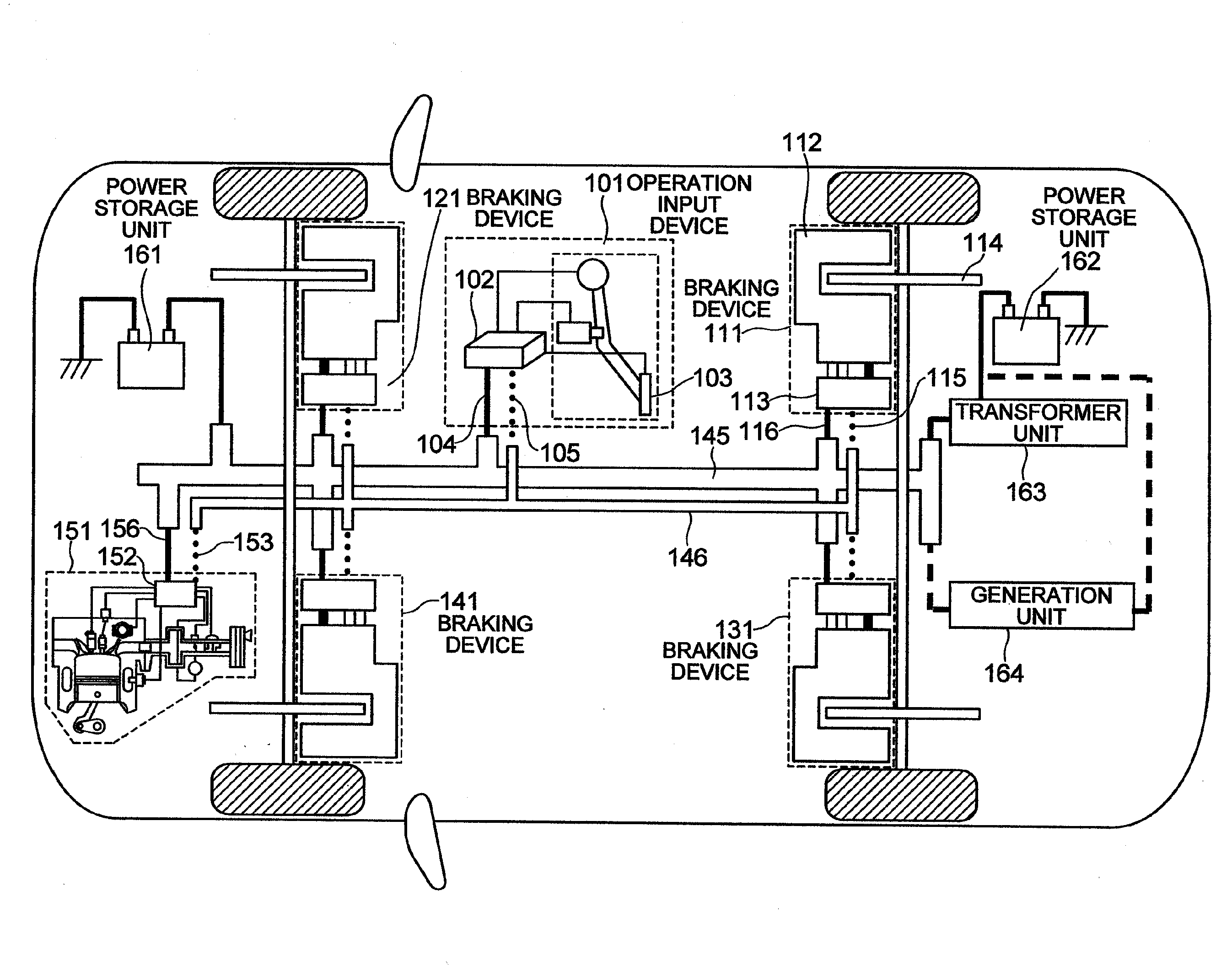
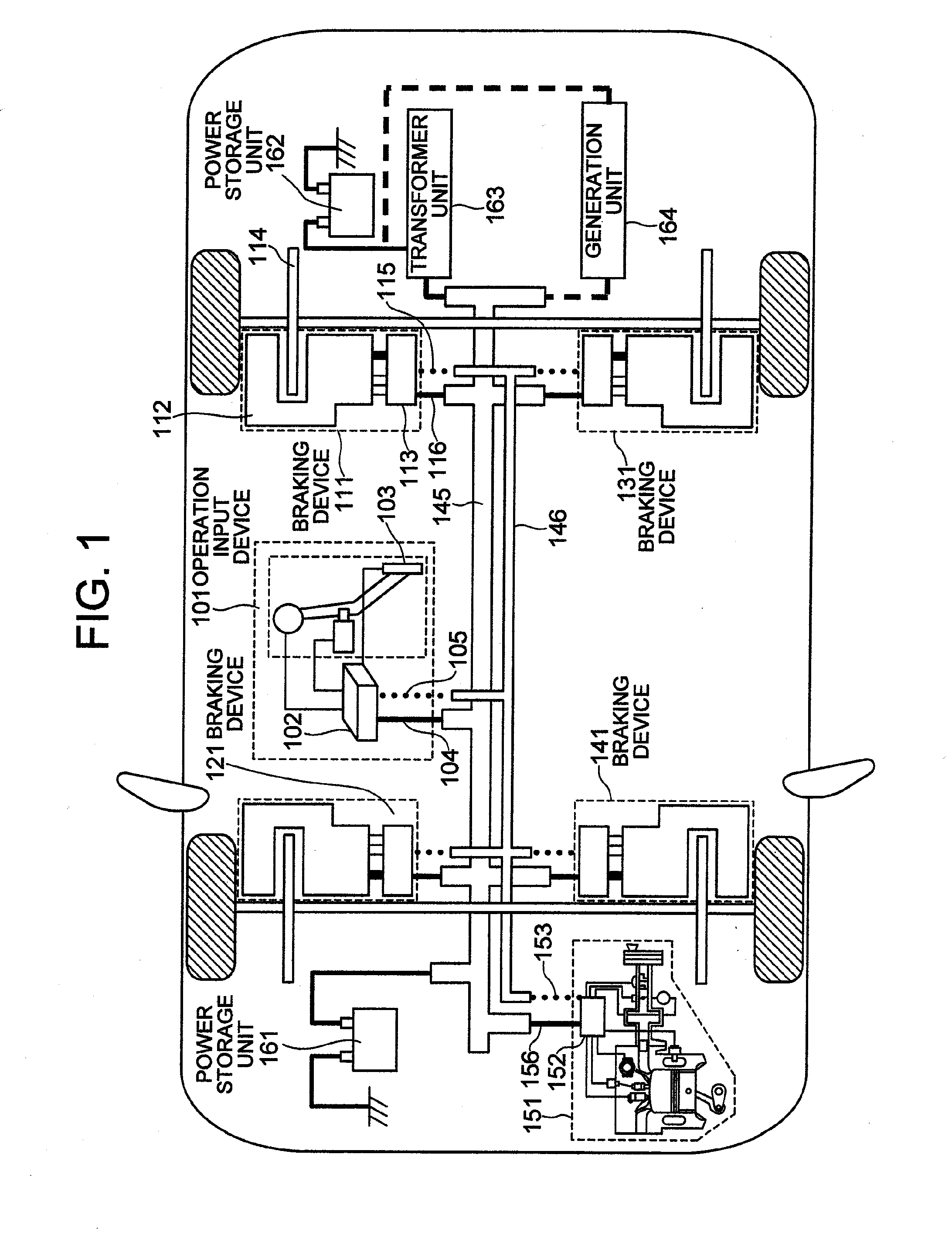
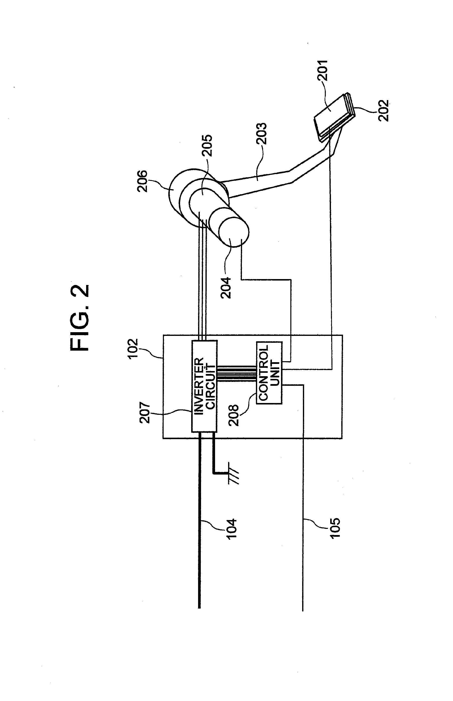
[0045]FIG. 1 schematically shows a vehicle system having an operation input device, one form of the on-vehicle actuator system of this invention. Reference number 101 represents an operation input device to be operated by a driver to drive the vehicle. It has an operation input unit 103 and a controller 102. The operation input device 101 can generate an operation reactionary force by a motor and also change it arbitrarily. The controller 102 receives or supplies electricity through a power supply wire 104 connected to a vehicle power supply system 145 and controls current and voltage of a motor of the operation input unit 103. The controller 102 also transmits information from the operation input device 101 to a vehicle output device via a communication path 105.

[0046]The operation input device 101 is not limited to a pedal device whose pedal position and pedal speed are changed by a force that the driver applies to the pedal, but may, for example, be a steering device whose steeri...

embodiment 2

[0153]FIG. 16 is a schematic diagram of a system according to embodiment 2. Denoted 801 is a motor-driven booster device and 802 a brake output device or an actuator mechanism having an input mechanism that the driver operates to drive a vehicle. The brake output device 802 has both functions of the brake output device and the operation input device. Designated 803 is an input mechanism operated by the driver when he or she drives the vehicle. This is a pedal in embodiment 2 but, depending on the system configuration, may employ a handle or lever. Denoted 831, 841, 851, 861 are calipers to generate a braking force in the vehicle. The motor-driven booster device 801 generates an operation reactionary force in the input mechanism 803 and also a hydraulic pressure in piping 807, 808. A hydraulic device 821 distributes a hydraulic pressure of piping 807, 808 to piping 823, 824, 825, 826. The hydraulic pressures in the piping 823, 824, 825, 826 act as piston thrusts for calipers 831, 841...


PUM


Abstract

A motor is controlled to always consume power supplied from a power supply system or not to supply power to the power supply system, by performing control to advance or delay a phase of a 3-phase current flowing in the motor or to reduce a percentage of the generated torque with respect to an effective value of the 3-phase current of the motor, or by applying a d-axis current to the motor.

Description

BACKGROUND OF THE INVENTION[0001]The present invention relates to an on-vehicle actuator system having a motor driven by a 3-phase current.[0002]As electronic and control technologies advance rapidly in recent years, a by-wire technology that can independently control an output mechanism on a vehicle side and an input mechanism on a driver's side during operations that determine vehicle actions such as driving, braking and steering. Since it can electronically control a relation between the driver's operations and vehicle movements, the by-wire technology can improve a feel and an operability when the driver drives a vehicle, thereby reducing fatigue of the driver. Independently of an intension of the driver, the by-wire technology can automatically apply brakes, run the vehicle at a constant speed, keep a constant distance from another car running in front and make the vehicle run along a traffic lane. It can also control an output of conventional output mechanisms to cooperate wit...

Claims


Application Information

Patent Timeline
Patent Type & Authority Applications(United States)
IPC IPC(8): H02P3/18
CPCB60L7/14B60L7/26B60L11/1803B60L2220/44Y02T10/7258B60L2260/28B60L2270/142Y02T10/7005B60L2250/26B60L50/51Y02T10/70Y02T10/72
Inventor UENO, KENTAROSASAKI, MITSUHIDEINNAMI, TOSHIYUKI
Owner HITACHI LTD
Why Eureka
Try Eureka