
High Power RF Solid State Power Amplifier System

a power amplifier and solid-state technology, applied in the direction of amplifiers with semiconductor devices only, amplifiers with semiconductor devices, amplifier protection circuit arrangements, etc., can solve the problems of enormous weight impact of such amplifiers on the overall system, and achieve the effect of reducing weight, significantly increasing operation power levels, and reducing power levels

Inactive Publication Date: 2009-01-29
NASA
View PDF16 Cites 11 Cited by
  • Summary
  • Abstract
  • Description
  • Claims
  • Application Information

AI Technical Summary

Benefits of technology

[0006]Generally speaking, one aspect of the invention concerns the provision of a solid state, high frequency power amplifier system wherein the operational power levels are significantly increased. In the latter regard, the systems constructed in accordance with the principles of the invention have the capability of generating tens or even hundreds of kilowatts of RF power. Moreover, these power levels can be generated with a solid state system of significantly reduced weight as compared with currently used vacuum tube amplifiers. A further important advantage of embodiments of the invention is that the power amplifier system provides a “graceful” degradation of output power, e.g., in the event of the failure of one or more stages in the system, the overall system continues to operate, albeit at a reduced power level.
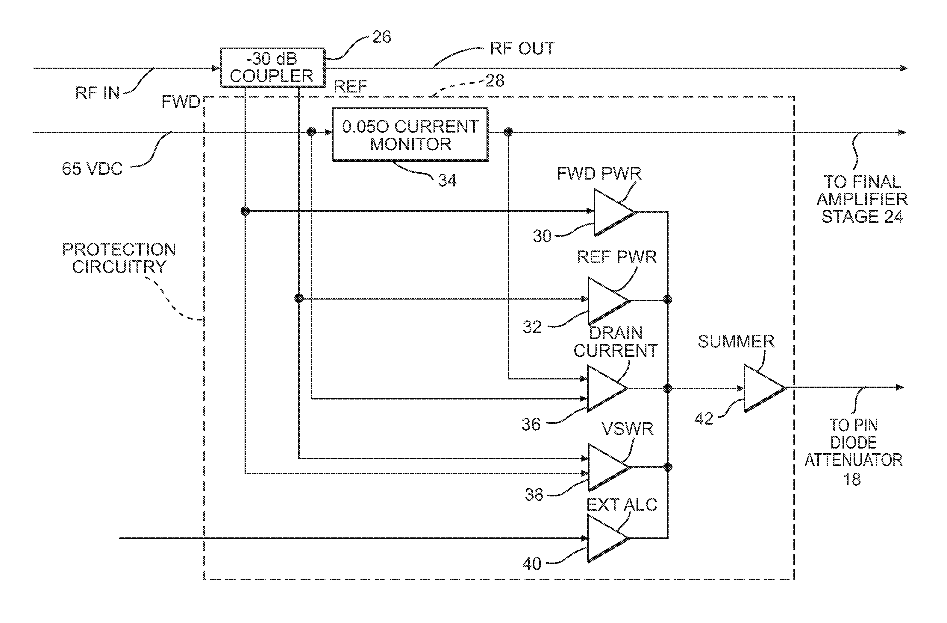
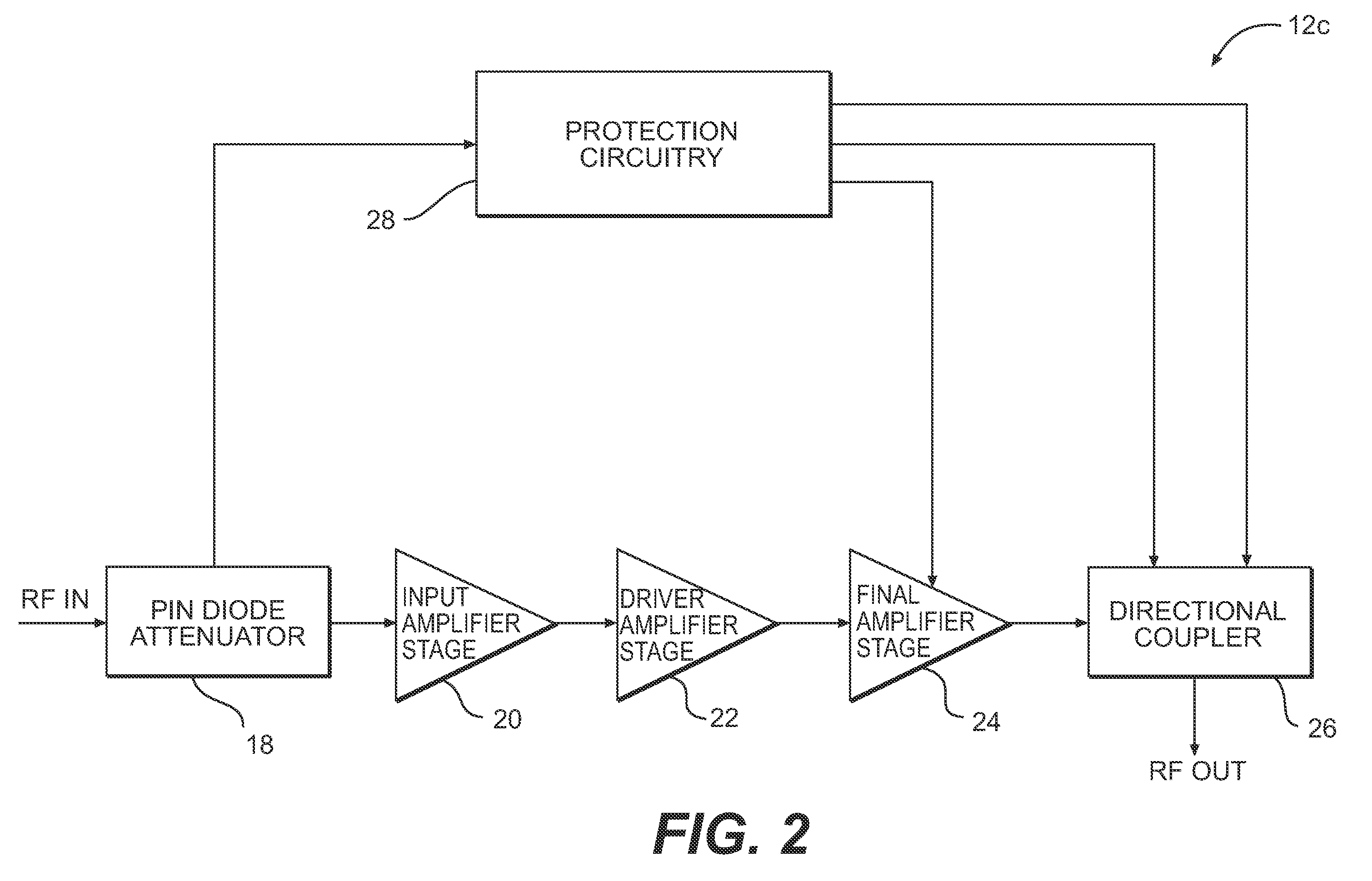
[0012]Preferably, the protection circuit protects the associated amplifier from excess power operation, high voltage standing wave ratio operation and high current.

Problems solved by technology

One serious drawback associated with vacuum tube amplifiers is the enormous weight impact of such amplifiers on the overall system.

Method used


Image

  • High Power RF Solid State Power Amplifier System
  • High Power RF Solid State Power Amplifier System
  • High Power RF Solid State Power Amplifier System

Examples


Embodiment Construction

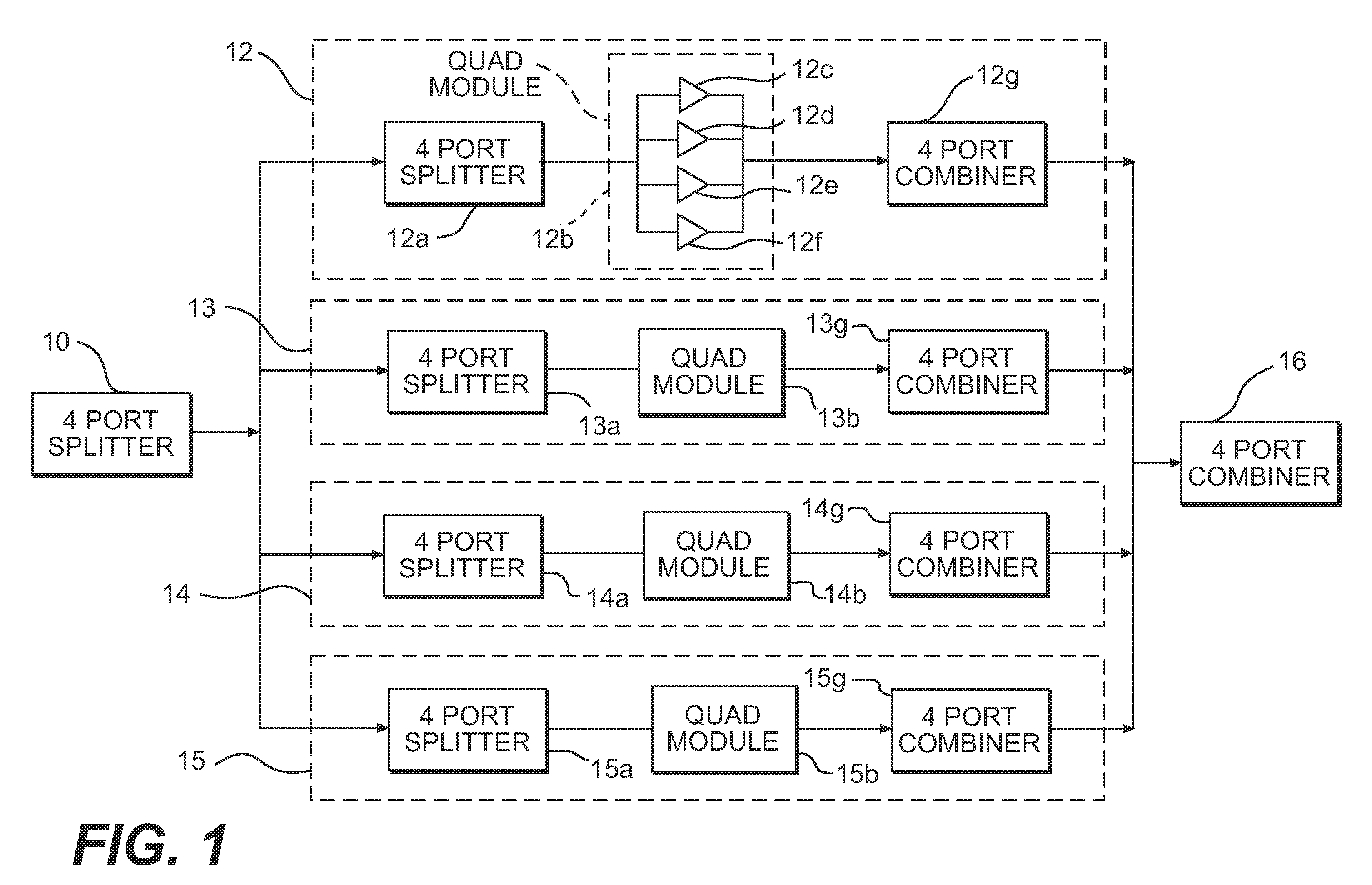
[0042]Referring to FIG. 1, there is shown a block diagram of a preferred embodiment of the overall system. The system includes a first four-port splitter 10 which receives a radio frequency (RF) input and the outputs of which are individually supplied to four modules 12, 13, 14 and 15. Modules 12 to 15 each comprise four power amplifier modules, referred to as quad modules, which are, in this specific embodiment, 1-kW (one kilowatt) modules. It will, of course, be understood that different modules and a different number of modules can be used.

[0043]Thus, considering module 12 as representative, module 12 includes a four-port power splitter or power divider 12a, a quad module 12b comprising four (e.g., 1 kW) power amplifier modules 12c, 12d, 12e and 12f, and a four-port power combiner 12g. Similarly, module 13 includes a four-port combiner or divider 13a, a quad module 13b, and four-port combiner 13g, and, as shown, modules 14 and 15 are also similar. Preferably, each of power divide...


PUM


Abstract

A high power, high frequency, solid state power amplifier system includes a plurality of input multiple port splitters for receiving a high-frequency input and for dividing the input into a plurality of outputs and a plurality of solid state amplifier units. Each amplifier unit includes a plurality of amplifiers, and each amplifier is individually connected to one of the outputs of multiport splitters and produces a corresponding amplified output. A plurality of multiport combiners combine the amplified outputs of the amplifiers of each of the amplifier units to a combined output. Automatic level control protection circuitry protects the amplifiers and maintains a substantial constant amplifier power output.

Description

CROSS-REFERENCES TO RELATED APPLICATIONS[0001]This application claims the benefit of U.S. Provisional Application Ser. No. 60 / 879,209 filed on Dec. 22, 2006.ORIGIN OF THE INVENTION[0002]The invention described herein was made in the performance of work under a NASA contract and by an employee of the United States Government and is subject to the provisions of Public Law 96-517 (35 U.S.C. § 202) and may be manufactured and used by or for the Government for governmental purposes without the payment of any royalties thereon ore therefore. In accordance with 35 U.S.C. §202, the contractor has elected not to retain title.FIELD OF THE INVENTION[0003]The present invention relates to power amplifiers and, more particularly, to solid state RF power amplifiers.BACKGROUND OF THE INVENTION[0004]Current state-of-the-art power amplifier systems incorporate only single modules to generate the required power output. The power output levels of solid state power amplifiers are quite low as compared w...

Claims


Application Information

Patent Timeline
Patent Type & Authority Applications(United States)
IPC IPC(8): H03F3/21H03F1/52
CPCH03F1/52H03F3/211H03F2200/408H03F2203/21142H03F2200/462H03F2203/21106H03F2200/444
Inventor SIMS, III, WILLIAM HERBERTCHAVERS, DONALD GREGORYRICHESON, JAMES J.
Owner NASA
Learn More