Immersion microscope objective and laser scanning microscope system using same

Active Publication Date: 2009-01-29
EVIDENT CORP
View PDF5 Cites 26 Cited by
  • Summary
  • Abstract
  • Description
  • Claims
  • Application Information

AI Technical Summary

Benefits of technology

[0020]The present invention relates to an immersion microscope objective for use in a laser scanning microscope that uses multiphoton excitation, as well as a multiphoton excitation laser scanning microscope system that uses such an immersion lens. The purpose of the present

Problems solved by technology

However, ultraviolet light is highly photo toxic and does not reach deep inside the brain.
However, microscopic observation using multiphoton excitation has some technical difficulties.
However, conventional optical glass has a low transmittance to ultraviolet light.
Therefore, the fluorescence to be detected is likely to be subject to Rayleigh scattering by the sample.
Even if it is assumed that an immersion microscope objective having a very large input

Method used


Image

  • Immersion microscope objective and laser scanning microscope system using same
  • Immersion microscope objective and laser scanning microscope system using same
  • Immersion microscope objective and laser scanning microscope system using same

Examples


embodiment 1

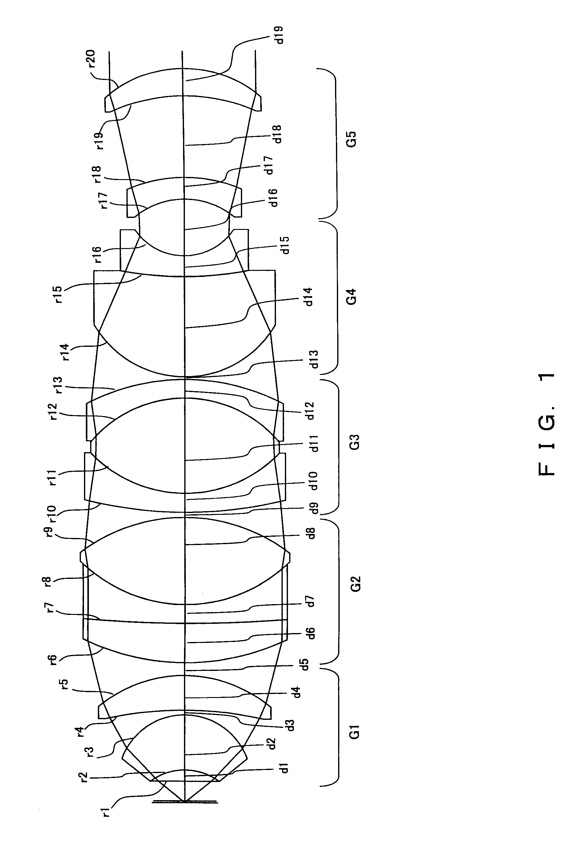
[0184]In Embodiment 1, as shown in the cross-sectional view of FIG. 1, the first lens group G1 is formed by a doublet (consisting of a piano-convex lens element and a meniscus lens element with its concave surface on the object side) and a meniscus lens element. The second lens group G2 is formed by a triplet (consisting of two meniscus lens elements with their concave surfaces on the image side and a lens element of positive refractive power). The third lens group G3 is formed by a triplet (consisting of a meniscus lens element with its concave surface on the image side, a biconvex lens element, and a meniscus lens element with its concave surface on the object side. The fourth lens group G4 is formed of a doublet (consisting of two meniscus lens elements with their concave surfaces on the image side). The fifth lens group G5 is formed of two meniscus lens elements with their concave surfaces on the object side. In this embodiment, the second lens group G2 moves relative to the fir...

embodiment 2

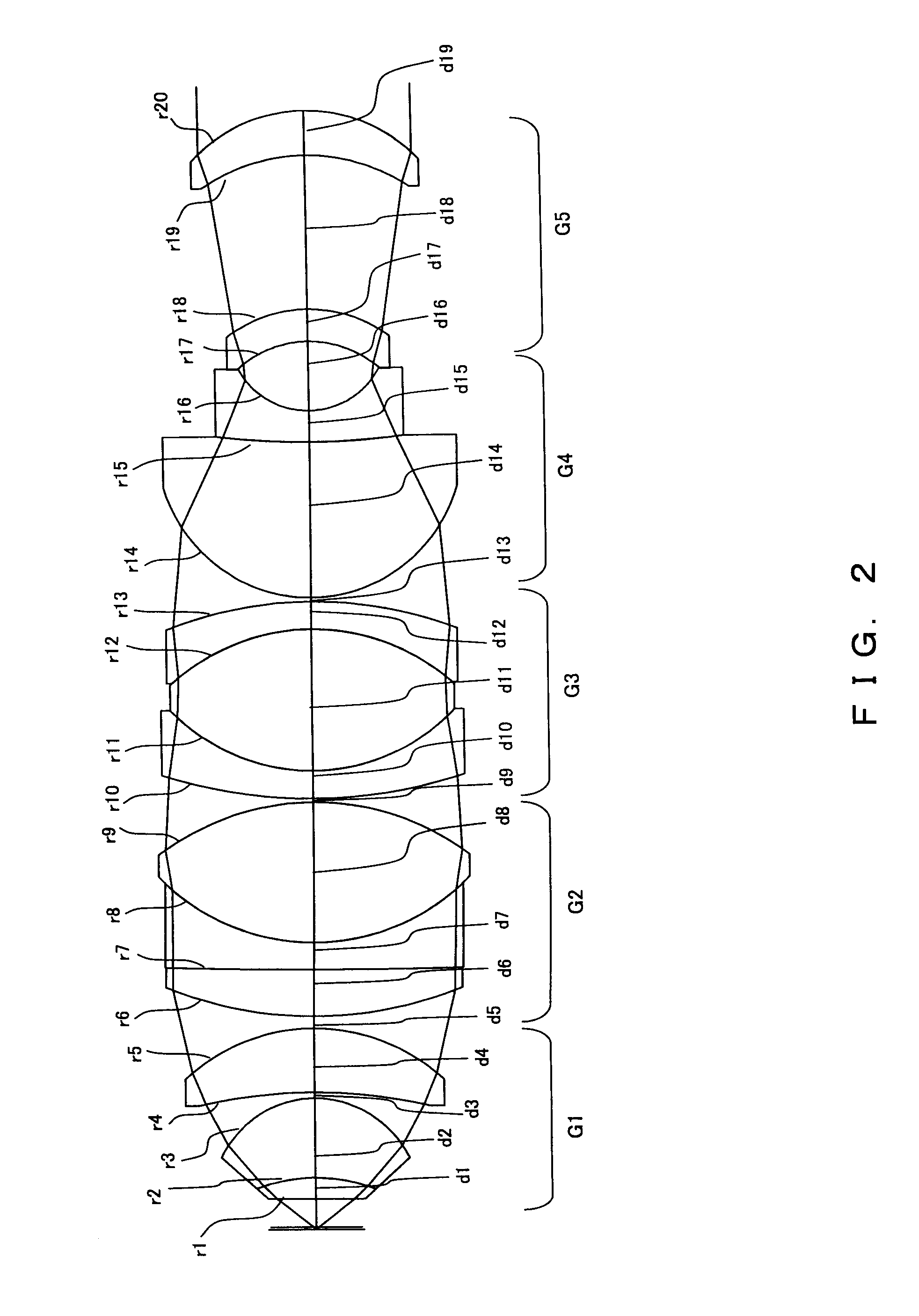
[0192]In Embodiment 2, as shown in a cross-sectional view of FIG. 2, the first lens group G1 is formed of a doublet (that consists of a plano-convex lens and a meniscus lens with its concave surface on the object side) and a meniscus lens element. The second lens group G2 consists of a triplet that is formed of two meniscus lens elements with their concave surfaces on the image side, and a biconvex lens. The third lens group G3 consists of a triplet that is formed of a meniscus lens element with its concave surface on the image side, a biconvex lens, and a meniscus lens element with its concave surface on the object side. The fourth lens group G4 consists of a doublet that is formed of two meniscus lens elements with their concave surfaces on the image side. The fifth lens group G5 includes two meniscus lens elements, each with its concave surface on the object side. The second lens group G2 moves relative to the positions of the first and third lens groups G1 and G3 so as to correc...

embodiment 3

[0199]In Embodiment 3, as shown in a cross-sectional view of FIG. 3, the first lens group G1 is formed of a doublet (that consists of a plano-convex lens element with its planar surface on the object side and a meniscus lens element with its concave surface on the object side) and a biconvex lens. The second lens group G2 is formed of a biconvex lens, a plano-concave lens with its concave surface on the object side, and a plano-convex lens. The third lens group G3 is formed by a triplet (that consists of a meniscus lens element with its concave surface on the image side, a biconvex lens element, and a meniscus lens element with its concave surface on the object side. The fourth lens group G4 is formed of a doublet that consists of a biconvex lens element and a biconcave lens element. The fifth lens group G5 is formed of a meniscus lens element with its concave surface on the object side and a biconvex lens element. The third lens group G3 moves along the optical axis relative to the...


PUM


Abstract

An immersion microscope objective formed of thirteen or fewer lens elements includes, in order from the object side, first and second lens groups of positive refractive power, a third lens group, a fourth lens group having negative refractive power with its image-side surface being concave, and a fifth lens group having positive refractive power with its object-side surface being concave. The first lens group includes, in order from the object side, a lens component that consists of a lens element of positive refractive power (when computed as being in air) and a meniscus lens element having its concave surface on the object side. Various conditions are satisfied to ensure that images of fluorescence, obtained when the immersion microscope objective is used in a laser scanning microscope that employs multiphoton excitation to observe a specimen, are bright and of high resolution. Various laser scanning microscopes are also disclosed.

Description

CROSS REFERENCE TO RELATED APPLICATIONS[0001]This application is based upon and claims the benefit of priority from the prior Japanese Patent Application No. 2007-186369 filed Jul. 17, 2007, No. 200:8-138231 filed May 27, 2008, and JP2006-179449 filed Jul. 9, 2008, the entire contents of which are incorporated herein by reference.BACKGROUND OF THE INVENTION[0002]1. Field of the Invention[0003]The present invention relates to an immersion microscope objective for use in a laser scanning microscope that uses multi-photon excitation.[0004]2. Description of the Related Art[0005]A known microscopic fluorescence observation means uses multiphoton excitation in fluorescence observation. During multiphoton excitation, a fluorescent object is illuminated with a light beam having wavelengths of integral multiples of an inherent absorption wavelength so as to cause excitation nearly equivalent to that caused by light having a wavelength equal to the inherent absorption wavelength. Multiphoton ...

Claims


Application Information

Patent Timeline
IPC IPC(8): G02B21/02G02B21/06
CPCG02B9/60G02B15/163G02B21/0032G02B21/33G02B21/02G02B15/145119
Inventor SAITO, MASAYOSHIYOKOI, EIJIKUSAKA, KENICHIHORIGOME, SHUHEISUGIZAKI, NORIYUKI
Owner EVIDENT CORP
Why Eureka
Try Eureka