Fluorescent nanocomposite

a fluorescent nanocomposite and nanocomposite technology, applied in the field of fluorescence nanocomposite, can solve the problems of limiting the availability of matching fluorophores for practical applications, affecting the quantum yield of fluorophores, and affecting the phototability of organic-based fluorophores, etc., to achieve the effect of reducing the quantitative yield of fluorophores

Active Publication Date: 2021-04-20
AGENCY FOR SCI TECH & RES
View PDF2 Cites 0 Cited by
  • Summary
  • Abstract
  • Description
  • Claims
  • Application Information

AI Technical Summary

Benefits of technology

[0008]Advantageously, the method may provide a nanocomposite having dual fluorescence properties depending on the aggregation state of the nanocomposite. Advantageously, the core of the nanocomposite may have relatively low fluorescence in dispersed form, while having relatively high fluorescence in aggregated form. In contrast, the shell of the nanocomposite may have relatively high fluorescence in dispersed form, while having relatively low fluorescence in aggregated form. In dispersed form, the nanocomposite may display the fluorescence properties of the shell, as the fluorescence of the shell would be much brighter than that of the core. In aggregated form, the nanocomposite may display the fluorescence properties of the core, as the fluorescence of the shell will be quenched and the fluorescence of the core will be enhanced.
[0104]The nanocomposite may exhibit photoluminescent properties in response to its aggregation state. The luciferin-like dye in the shell may show intense green emission (λem=520 nm, Quantum Yield (QY)=0.20) in solution which may be completely quenched upon aggregation. In contrast, the gold nanocluster in the core may display relatively weak red emission in solution (λem=720 nm) which may be greatly enhanced upon aggregation.

Problems solved by technology

However, both organic-based and inorganic-based materials have their own intrinsic limitations.
For example, organic-based fluorophores often have poor photostability.
This restricts the availability of matching fluorophores for practical applications.
Further advantageously, since no toxic elements are used in the method, the method may be biocompatible.

Method used


Image

  • Fluorescent nanocomposite
  • Fluorescent nanocomposite
  • Fluorescent nanocomposite

Examples


example 1

and Methods

[0121]Materials

[0122]Gold (III) chloride solution (HAuCk4, 30% in dilute HCl), L-glutathione (GSH, 98%), L-cysteinyl-L-glycine (Cys-Gly, 85%), L-γ-glutamyl-L-cysteine (γ-Glu-Cys, 80%), L-cysteine (Cys, 97%), and quinine sulphate (QS, 98%), D-luciferin (99%) were purchased from Sigma-Aldrich. Hydroquinone (HQ, benzene-1,4-diol, 99.5%) was purchased from Acros Organic.

[0123]All reagents were used as received and without further purification. All glassware were washed with Aqua Regia (HCl:HNO3 volume ratio=3:1) and rinsed with ethanol and ultrapure water. Ultrapure water with a specific resistance of 18.2 MΩ was used throughout the experiment.

[0124]“AuNC@dye” refers to a gold nanocluster coated with a fluorescent dye.

[0125]Methods

[0126]Physical Characterization

[0127]UV-Vis absorption and photoluminescence (PL) spectra were recorded on a Shimadzu UV-2450 spectrometer and an Infinite® M200 plate reader (from Tecan), respectively. Transmission electron microscopy (TEM) images w...

example 2

of the Hybrid Nanocomposite

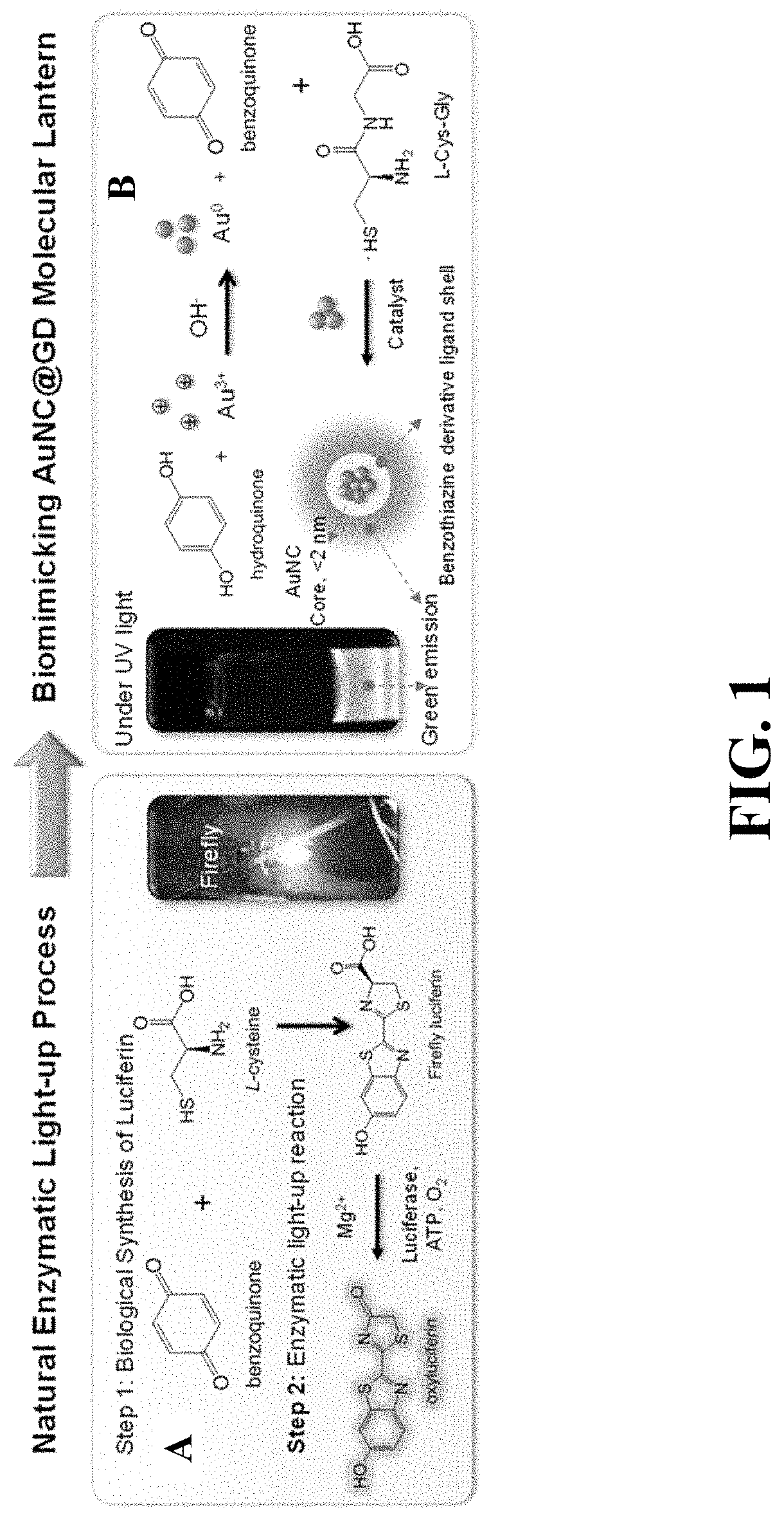
[0132]A biotemplating method is used to synthesize the nanocomposite at room temperature using gold chloride (HAuCl4), hydroquinone, and a cysteine-containing peptide (e.g., Cys-Gly). A schematic diagram of the synthesis is shown in FIG. 1.

[0133]Aqueous solutions of HAuCl4 (20 mM, 50 μL), Hydroquinone (20 mM, 50 μL) and Cys-Gly (20 mM, 150 μL) were sequentially added into a glass vial containing ultrapure water under constant stirring at 500 rpm. Then aliquots of NaOH (1 M, 20 μL) were added into the mixture to trigger the reaction. The volume of the final reaction mixture was adjusted to 1 mL. An aqueous solution of strong green-emitting AuNC protected by dye molecules (AuNC@dye) was formed and collected after 24 hours of reaction. The AuNC@dye product was dialyzed using a Fisher dialysis tubing with a molecular weight cut-off (MWCO) of 6 kDa for further use.

example 3

ization of the Hybrid Nanocomposite

[0134]Size Distribution

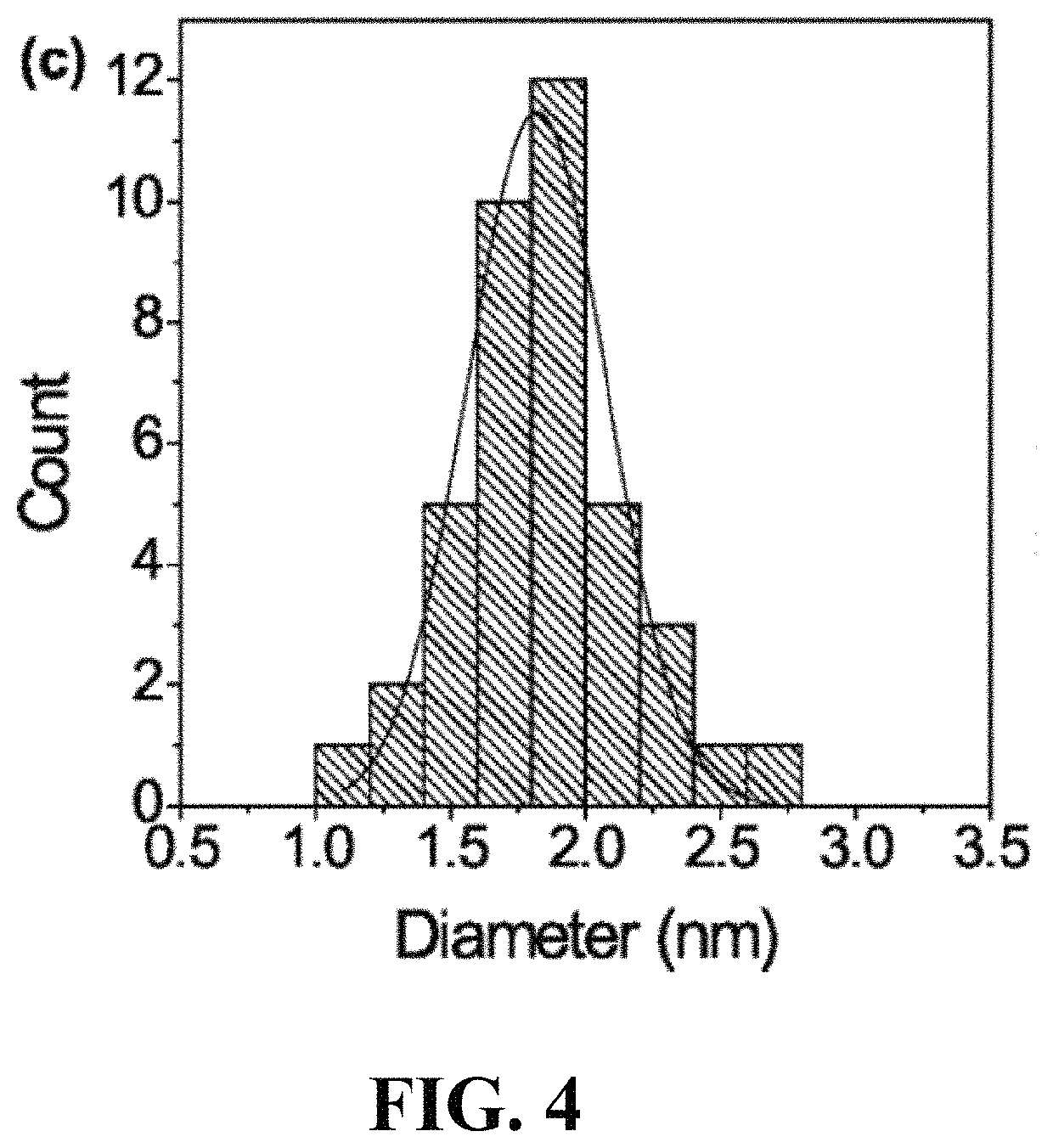
[0135]Transmission electron microscopy (TEM) was first used to characterize the size of the AuNC@dye. FIG. 3A and FIG. 3B are TEM images of the nanocomposite at different magnifications. A small aliquot of the nanocomposite was dropped on a copper grid and air-dried prior to TEM measurement. As shown in FIG. 3, the synthesized Au particles are very small in size and no large particles were observed. Analysis of the high resolution TEM image (FIG. 3B) gives an average diameter of 1.82±0.02 nm for these Au particles (FIG. 4), which confirms the as-synthesized particles are AuNCs.

[0136]UV-Vis and Fluorescence Spectroscopy

[0137]The formation of AuNCs was also confirmed by the UV-vis spectrum. It is well documented that Au nanoparticles (AuNPs) with core size larger than 2 nm show a distinct peak near 520 nm on their UV-vis spectra due to surface plasmon resonance (SPR). However, no SPR peaks are observed on the UV-vis spectrum, w...


PUM

PropertyMeasurementUnit
diameteraaaaaaaaaa
molecular weight cut-offaaaaaaaaaa
core sizeaaaaaaaaaa

Abstract

The present invention relates to a method for forming a nanocomposite having a core-shell structure, the method comprising the steps of: forming a core comprising a first fluorophore capable of aggregation induced emission, and depositing a second fluorophore capable of aggregation caused quenching onto the surface of the core to form a shell at least partially surrounding the core. The present invention also relates to a nanocomposite obtained by said method, and a method of altering the fluorescence of said nanocomposite. The nanocomposite may exhibit dual emission colours and opposite aggregation fluorescent behaviours.

Description

TECHNICAL FIELD[0001]The present invention relates to a method for forming a nanocomposite having a core-shell structure, the method comprising the steps of: forming a core comprising a first fluorophore capable of aggregation induced emission, and depositing a second fluorophore capable of aggregation caused quenching onto the surface of the core to form a shell at least partially surrounding the core. The present invention also relates to a nanocomposite obtained by said method.BACKGROUND ART[0002]Fluorophores are useful due to a variety of important applications such as bioimaging, smart sensing, security inks, dye sensitized solar cells, and light-emitting diodes (LED). Conventional fluorophores are either organic-based materials, for example organic dyes, fluorescent proteins, and aggregation induced emission dyes, or inorganic-based materials, for example semiconductor quantum dots and upconversion nanoparticles. However, both organic-based and inorganic-based materials have t...

Claims


Application Information

Patent Timeline
Patent Type & Authority Patents(United States)
IPC IPC(8): C09K11/58C09K11/06
CPCC09K11/58C09K11/06C09K2211/1018
Inventor YU, YONGTAN, YEN NEE
Owner AGENCY FOR SCI TECH & RES
Why Eureka
Try Eureka