Optical waveguide ring resonator with photo-tunneling input/output port

a technology of optical waveguides and resonators, applied in the field of optical waveguides and photonic circuits, can solve the problems of general loss of optical signal energy within the resonator, loss of optical signal energy degrade the performance of the resonator, and limit the utility of the resonator in some applications

Active Publication Date: 2009-01-29
HEWLETT-PACKARD ENTERPRISE DEV LP
View PDF13 Cites 13 Cited by
  • Summary
  • Abstract
  • Description
  • Claims
  • Application Information

AI Technical Summary

Problems solved by technology

Optical loss results in a general loss of optical signal energy within the resonator.
Loss of the optical signal energy degrades a performance of the resonator and may limit its utility in some applications.
In part, optical loss in a ring resonator may be due in part to waveguide loss.
Among the sources of waveguide loss are material loss and scattering loss.
Material loss occurs when the optical signal is either absorbed or scattered by a material of the optical waveguide.
On the other hand, scattering loss is caused by a destructive interaction between the optical signal and a physical boundary of another physical structure of the optical waveguide.
Scattering loss generally impedes propagation of the optical signal.
Tight coupling between the opti

Method used


Image

  • Optical waveguide ring resonator with photo-tunneling input/output port
  • Optical waveguide ring resonator with photo-tunneling input/output port
  • Optical waveguide ring resonator with photo-tunneling input/output port

Examples


Embodiment Construction

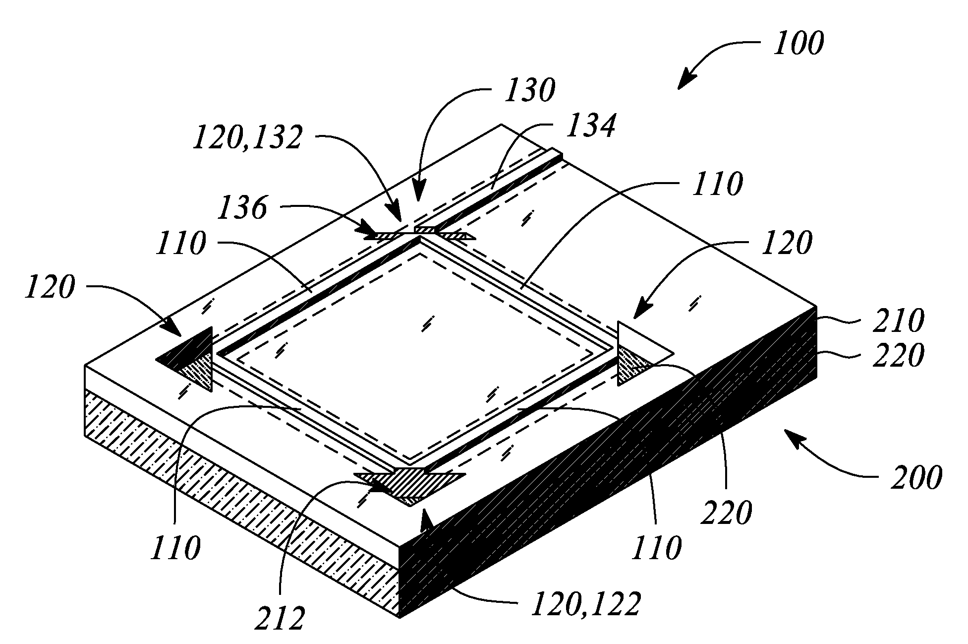
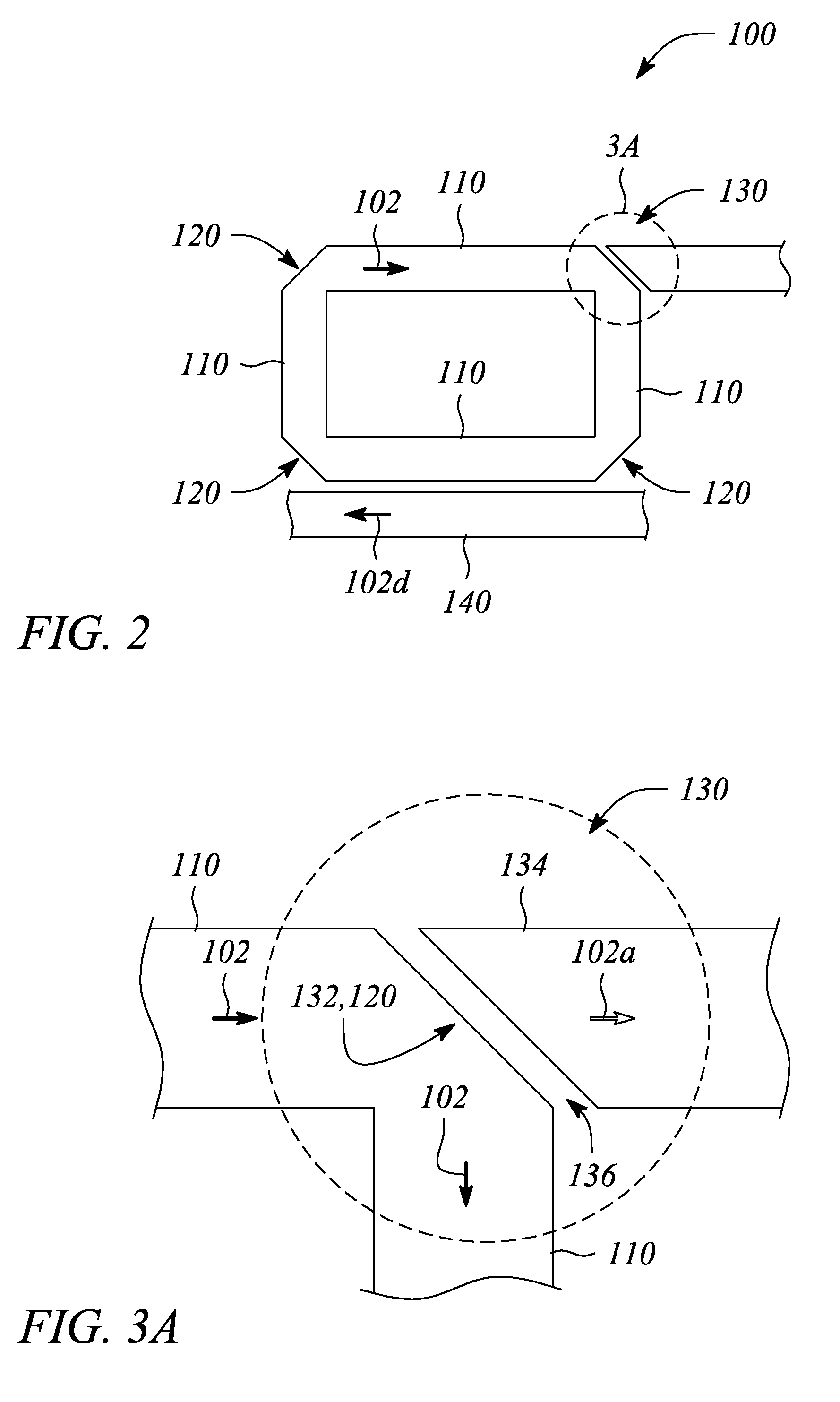
[0028]Embodiments of the present invention employ optical waveguide segments and total internal reflection (TIR) mirrors to realize an optical resonator having low optical loss. In particular, the optical resonator of the present invention is a closed loop, ring-shaped resonant structure that supports a propagating optical signal within the closed loop. In various embodiments of the optical resonator according to the present invention, one or more input / output ports (I / O ports) are provided. The I / O port(s) facilitate one or both of introducing to and extracting from the optical resonator the propagating optical signal or a portion thereof.

[0029]The optical resonator according to various embodiments of the present invention has a relatively compact and space-efficient form factor. Moreover, the optical resonator may be readily fabricated in an integrated form as part of a larger circuit or subsystem. In particular, the optical resonator, according to various embodiments of the prese...


PUM


Abstract

An optical resonator, a photonic system and a method of optical resonance employ optical waveguide segments connected together with total internal reflection (TIR) mirrors to form a closed loop. The optical resonator includes the optical waveguide segments, the TIR mirrors and a photo-tunneling input/output (I/O) port. The photo-tunneling I/O port includes one of the TIR mirrors. The method includes propagating and reflecting an optical signal, or a portion thereof, in the optical resonator, and transmitting a portion of the optical signal through the photo-tunneling I/O port. The photonic system includes the optical resonator and a source of an optical signal.

Description

CROSS-REFERENCE TO RELATED APPLICATIONS[0001]The present invention is related to patent application of Wu et al., entitled “Optical Waveguide Ring Resonator with Optical Gain” (Attorney Docket No. 200701511), filed concurrently herewith, which is incorporated by reference herein in its entirety.STATEMENT REGARDING FEDERALLY SPONSORED RESEARCH OR DEVELOPMENT[0002]N / ABACKGROUND[0003]1. Technical Field[0004]The invention relates to optical waveguides and photonic circuits. In particular, the invention relates to optical waveguide resonators used in photonic systems.[0005]2. Description of Related Art[0006]An optical ring resonator generally comprises a segment or segments of optical waveguide arranged in a ring-shape or essentially a closed loop. Such ring resonators have a variety of important uses in photonic systems. For example, the ring resonator may be part of a photonic filter. In another example, the ring resonator may be employed to one or more of generate, modulate or amplify...

Claims


Application Information

Patent Timeline
IPC IPC(8): G02B6/26H01S3/083
CPCG02B6/12007H01S5/1071H01S5/026G02B2006/12104
Inventor WU, WEIWANG, SHIH-YUANTY TAN, MICHAEL RENNEFATTAL, DAVID A.
Owner HEWLETT-PACKARD ENTERPRISE DEV LP
Why Eureka
Try Eureka