Controller of driving device for vehicle

a control device and vehicle technology, applied in the direction of dynamo-electric gear control, gear control, instruments, etc., can solve the problems of deteriorating fuel economy of the vehicle, inability to provide any power transmission mechanism having the advantages, and the vehicular drive system suffering from a similar problem, so as to improve the efficiency of the continuously variable shifting control of the continuously variable transmission portion, the effect of reducing the required size of the second electric motor

Inactive Publication Date: 2009-01-29
TOYOTA JIDOSHA KK
View PDF3 Cites 18 Cited by
  • Summary
  • Abstract
  • Description
  • Claims
  • Application Information

AI Technical Summary

Benefits of technology

[0009]In the vehicular drive system constructed as described above, the continuously-variable transmission portion of the vehicular drive system is switchable by the differential limiting device, between a differential state in which the differential mechanism is operable to perform the differential function without a limitation, that is, a continuously-variable shifting state in which the continuously-variable transmission portion is operable as the electrically controlled continuously variable transmission, and a non-differential state such as a locked state in which the differential mechanism is not operable to perform the differential function, that is, a non-continuously-variable shifting state in which the continuously-variable transmission portion is not operable as the electrically controlled continuously variable transmission. Accordingly, the vehicular drive system has both an advantage of improved fuel economy provided by a transmission the speed ratio of which is electrically variable, and an advantage of high power transmitting efficiency provided by a gear type power transmitting device constructed for mechanical transmission of power.
[0057]Preferably, the step-variable transmission portion is a step-variable automatic transmission. In this case, the overall speed ratio of the vehicular drive system is changed in steps when the step-variable transmission portion is shifted. The change of the overall speed ratio in steps is more rapid than when the overall speed ratio is continuously changed. Accordingly, the drive system functions as a continuously variable transmission capable of smoothly changing the vehicle drive torque, and also capable of changing the speed ratio in steps for rapidly obtaining the vehicle drive torque.

Problems solved by technology

However, there is not available any power transmitting mechanism having the advantages of those two types of transmission.
It is also noted that a portion of the output of the engine is once converted into an electric energy which is subsequently converted into a mechanical energy to be transmitted to the drive wheels, whereby the fuel economy of the vehicle may possibly be deteriorated under some running condition of the vehicle, for instance, during a high-speed running of the vehicle.
Where the above-described differential mechanism is a transmission the speed ratio of which is electrically variable, for example, a continuously variable transmission so-called an “electric CVT”, the vehicular drive system suffers from a similar problem.

Method used


Image

  • Controller of driving device for vehicle
  • Controller of driving device for vehicle
  • Controller of driving device for vehicle

Examples


embodiment 1

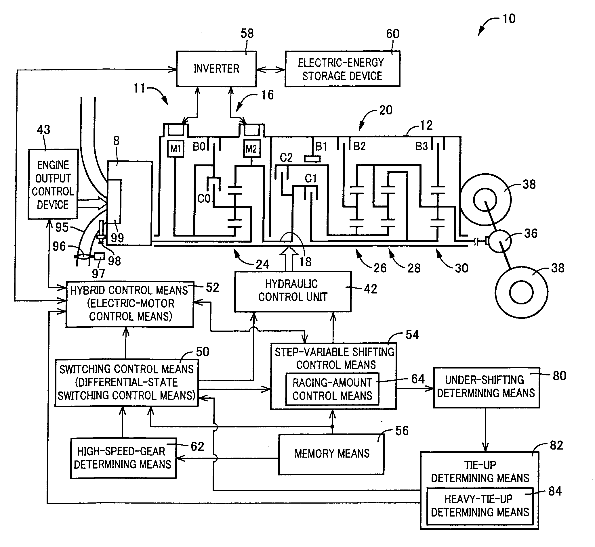
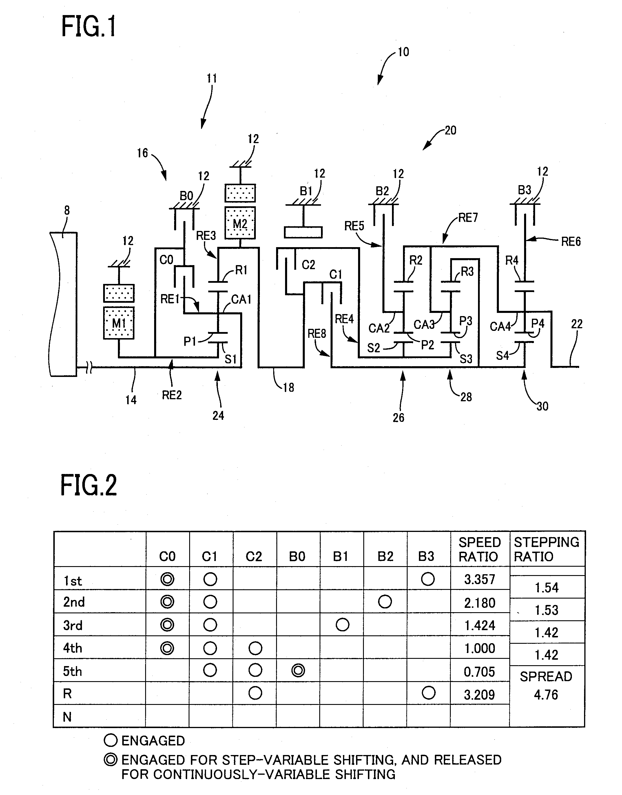
[0095]FIG. 1 is s schematic view for explaining an a transmission mechanism 10 constituting a part of a drive system for a hybrid vehicle, which drive system is controlled by a control apparatus according to one embodiment of this invention. As shown in FIG. 1, the transmission mechanism 10 includes: an input rotary member in the form of an input shaft 14; a continuously-variable transmission portion in the form of a differential portion 11 connected to the input shaft 14 either directly, or indirectly via a pulsation absorbing damper (vibration damping device) not shown; a step-variable transmission portion in the form of an automatic transmission portion 20, which functions as a multiple-step transmission disposed between the differential portion 11 and drive wheels 38 of the vehicle, and which is connected in series via a power transmitting member 18 (power transmitting shaft) to the transmission portion 11 and the drive wheels 38; and an output rotary member in the form of an ou...

embodiment 2

[0211]In the first embodiment described above, the differential portion 11 is switched to the continuously-variable shifting state to reduce the influence of the tie-up phenomenon of the automatic transmission portion 20 on the engine 8, for reducing the shock of the clutch-to-clutch shifting action, when the clutch-to-clutch shifting action of the automatic transmission portion 20 is brought into the tie-up state in the non-continuously-variable shifting state of the differential portion 11. To reduce the influence of the tie-up phenomenon of the automatic transmission portion 20, however, the differential portion 11 need not be switched to the non-continuously variable shifting state, provided the engine speed NE can be controlled as needed, irrespective of a change of the rotating speed of the rotary element of the automatic transmission portion 20, by cutting off the power transmitting path between the automatic transmission portion 20 and the engine 8, for example.

[0212]When th...

embodiment 3

[0242]In the preceding embodiments, the differential portion 11 is switched to the continuously-variable shifting state, or the input clutch which permits or inhibits the power input from the differential portion 11 to the automatic transmission portion 20 is released or partially engaged, when the clutch-to-clutch shifting action of the automatic transmission portion 20 is in the tie-up state while the differential portion 11 is placed in the non-continuously-variable shifting state. Thus, the influence of the tie-up phenomenon of the automatic transmission portion 20 on the engine 8 is reduced to reduce the shifting shock.

[0243]However, the engine speed NE may be influenced by a shifting action of the automatic transmission portion, leading to generation of the shifting shock, even when the shifting action of the automatic transmission portion 20 is not in the tie-up state.

[0244]In a well known power transmitting system provided with a torque converter, a fluid coupling or any oth...


PUM


Abstract

A transmission mechanism including a switching clutch or brake that is switchable between a continuously-variable shifting state and a step-variable shifting state, and has both an advantage of improved fuel economy provided by a transmission, the speed ratio of which is electrically variable, and an advantage of high power transmitting efficiency provided by a gear type power transmitting device constructed for mechanical transmission of power. While a clutch-to-clutch shifting action of an automatic transmission portion is in a tie-up state, a differential portion is placed in a continuously-variable shifting state by switching control, and engine speed is changed under the control of hybrid control, so as to prevent a drop of the engine speed for thereby reducing a shock of the shifting action, unlike in a non-continuously-variable shifting state of the differential portion in which the engine speed is directly influenced by the tie-up state.

Description

TECHNICAL FIELD[0001]The present invention relates to a vehicular drive system including a differential mechanism operable to perform a differential function, and electric motors, and more particularly to techniques for reducing the sizes of the electric motors.BACKGROUND ART[0002]There is known a drive system for a vehicle, which includes a differential mechanism operable to distribute an output of an engine to a first electric motor and its output shaft, and a second electric motor disposed between the output shaft of the differential mechanism and drive wheels of the vehicle. Patent Document 1 discloses an example of such a vehicular drive system, which is a hybrid vehicle drive system. In this hybrid vehicle drive system, the differential mechanism is constituted by a planetary gear set, for example, and a major portion of a drive force of the engine is mechanically transmitted to the drive wheels through the differential function of the differential mechanism, while the rest of...

Claims


Application Information

Patent Timeline
Patent Type & Authority Applications(United States)
IPC IPC(8): B60W10/10B60W10/02G06F17/00B60K6/445B60K6/547B60L15/20B60L50/16B60W10/00B60W10/08B60W10/101B60W10/11B60W10/115B60W20/00F16D48/02F16H59/68F16H61/02F16H61/04F16H61/66F16H61/68F16H61/684F16H61/686F16H63/40F16H63/50
CPCB60K1/02Y10T477/32B60K6/445B60K6/547B60W10/02B60W10/10B60W20/00F16H3/728F16H61/0437F16H61/686F16H2037/0873F16H2200/0047F16H2200/2012F16H2200/2048Y02T10/7258Y02T10/6239Y10S903/918Y10T477/6203Y10T477/33Y10T477/27B60K6/365B60L15/2045B60L15/2054B60L2220/42B60L2240/421B60L2240/423B60L2240/441B60L2240/443B60L2240/507F16H3/66F16H2200/0043F16H2200/2007F16H2200/201F16H2200/2046Y02T10/62Y02T10/64Y02T10/72B60K6/543B60W20/40
Inventor TABATA, ATSUSHIKAMADA, ATSUSHIINOUE, YUJI
Owner TOYOTA JIDOSHA KK
Why Eureka
Try Eureka