Ultrasonic probe, ultrasonic endscope, and ultrasonic diagnostic apparatus

a technology of ultrasonic probes and endoscopes, applied in the field of ultrasonic probes, ultrasonic endoscopes, ultrasonic diagnostic equipment, etc., can solve the problems of increasing the temperature of ultrasonic probes, affecting the cooling efficiency of instruments, and wasting energy

Inactive Publication Date: 2009-01-29
FUJIFILM CORP
View PDF3 Cites 17 Cited by
  • Summary
  • Abstract
  • Description
  • Claims
  • Application Information

AI Technical Summary

Benefits of technology

[0028]According to the present invention, since the cooling mechanism including the porous member is provided between the ultrasonic transducer array and the backing material, and thereby, the ultrasonic transducers can be cooled while provi...

Problems solved by technology

Not the whole energy of the drive signals is converted into acoustic energy and the considerable amount of energy turns into heat.
Thus, there has been a problem of rising temperature of the ultrasonic probe during its use.
However, in JP-P2002-291737A, only a small portion of the ultrasonic probe head part is indirectly cooled via the cable by the cable cooling, and therefore, the cooling efficiency is not very good.
However, when the cooling pipe is provided on the side of the group of ultrasonic vibrators (FIG. 3), the thermal coupling between the cooling pipe and the group of ultrasonic vibrators becomes weaker and the cooling efficiency is not good.
On the other hand, when the cooling pipe is provided on the back of the group of ultrasonic vibrators (FIGS. 4-6), there is a fear that the ultrasonic waves released to the back of the group of ultrasonic vibrators may not be sufficiently absorbed.
Therefore, the vibrator part is indirectly cooled ...

Method used


Image

  • Ultrasonic probe, ultrasonic endscope, and ultrasonic diagnostic apparatus
  • Ultrasonic probe, ultrasonic endscope, and ultrasonic diagnostic apparatus
  • Ultrasonic probe, ultrasonic endscope, and ultrasonic diagnostic apparatus

Examples


first embodiment

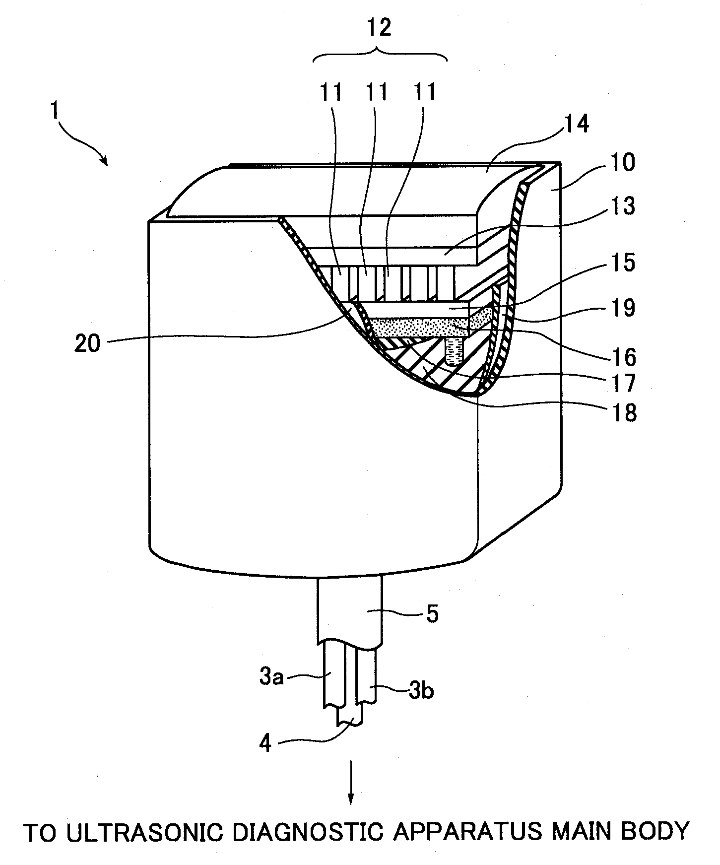
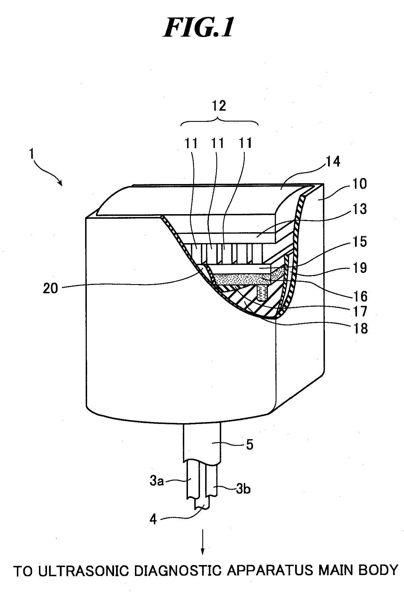
[0041]FIG. 1 is a perspective view showing an exterior appearance and part of an interior of an ultrasonic probe according to the present invention. The ultrasonic probe 1 is used in contact with an object to be inspected when extracavitary scanning is performed. As shown in FIG. 1, a head part of the ultrasonic probe 1 includes a casing 10, an ultrasonic transducer array 12 including plural ultrasonic transducers (vibrators) 11, a first acoustic matching layer 13, an acoustic lens 14, a second acoustic matching layer 15, a micro-channel 16 as a cooling mechanism for cooling the plural ultrasonic transducers 11, a third acoustic matching layer 17, a backing material 18, flexible printed circuits (FPCs) 19 connected to a common electrode of the plural ultrasonic transducers 11, and FPCs 20 connected to signal electrodes of the plural ultrasonic transducers 11.

[0042]In the embodiment, in order to cool the plural ultrasonic transducers 11, the micro-channel 16 is formed on the back of ...

second embodiment

[0063]Next, the present invention will be explained.

[0064]FIG. 5 (a) is a front view showing an interior of a head part of the ultrasonic probe according to the second embodiment of the present invention. Further, FIG. 5 (b) is a plan sectional view of the ultrasonic probe along the dashed-dotted line 5B-5B′ shown in FIG. 5 (a), and FIG. 5 (c) is a side sectional view of the ultrasonic probe along the dashed-dotted line 5C-5C′ shown in FIG. 5 (a). In FIG. 5 (a), an acoustic matching layer 43 and an acoustic lens 44 shown in FIG. 5 (b) are omitted.

[0065]As shown in FIG. 5 (a), the ultrasonic probe according to the second embodiment of the present invention has an ultrasonic transducer array 42 in which plural ultrasonic transducers 11 are two-dimensionally arranged, and accordingly, the micro-channel configuration formed within the ultrasonic probe is different from that in the first embodiment. The connection configuration between the ultrasonic probe and the ultrasonic diagnostic a...


PUM


Abstract

In an ultrasonic probe to be used in an ultrasonic diagnostic apparatus for medical use, ultrasonic transducers are cooled while sufficiently absorbing ultrasonic waves released to the back of the ultrasonic transducers without causing attenuation of ultrasonic waves transmitted or received by the ultrasonic transducers. The ultrasonic probe includes: an ultrasonic transducer array including plural ultrasonic transducers for transmitting and receiving ultrasonic waves; an acoustic matching layer provided on a front of the ultrasonic transducer array; a cooling mechanism directly or indirectly provided on a back of the ultrasonic transducer array and including a porous member; a backing material provided on the back of the ultrasonic transducer array via at least the cooling mechanism; and channels for circulation of a liquid heat transfer material in the cooling mechanism.

Description

BACKGROUND OF THE INVENTION[0001]1. Field of the Invention[0002]The present invention relates to an ultrasonic probe to be used when intracavitary scanning or extracavitary scanning is performed on an object to be inspected, and an ultrasonic endoscope to be inserted into a body cavity of the object. Further, the present invention relates to an ultrasonic diagnostic apparatus including such an ultrasonic probe or ultrasonic endoscope and an ultrasonic diagnostic apparatus main body.[0003]2. Description of a Related Art[0004]In medical fields, various imaging technologies have been developed in order to observe the interior of an object to be inspected for making diagnoses. Especially, ultrasonic imaging for acquiring interior information of the object by transmitting and receiving ultrasonic waves enables image observation in real time and provides no exposure to radiation unlike other medical image technologies such as X-ray photography or RI (radio isotope) scintillation camera. A...

Claims


Application Information

Patent Timeline
IPC IPC(8): A61B8/14
CPCA61B1/05A61B1/06A61B1/12A61B8/0841A61B8/445A61B8/4281A61B8/4455A61B8/4488A61B8/546A61B8/12
Inventor HYUGA, HIROAKI
Owner FUJIFILM CORP
Why Eureka
Try Eureka