Storage control unit with memory cash protection via recorded log

a storage control unit and recorded log technology, applied in the direction of memory address/allocation/relocation, instruments, error detection/correction, etc., can solve the problems of accompanied latency delays in response, media primarily encounter time delays in reading or writing data, and data access was much faster, so as to reduce bandwidth requirements

Inactive Publication Date: 2009-01-29
DIGI DATA CORP
View PDF17 Cites 104 Cited by
  • Summary
  • Abstract
  • Description
  • Claims
  • Application Information

AI Technical Summary

Benefits of technology

[0008]During the 1970's it was noted that a considerable performance advantage could be derived by using a memory cache within control unit(s), also termed storage controller(s), as an intermediary storage location instead of directly accessing disk. Once the data was staged to the memory established for this intermediary role, access to the data was much quicker than by reading or writing disk with the accompanied latency delays in response.
[0056]A still further feature of embodiments of the above describe invention is that said journaling operations do not require overhead operations of ones of said storage controllers other than a respective one of said storage controllers performing the journaling operations.

Problems solved by technology

Thus, each of the disk devices, with rotating media predominantly encounters time delays in reading or writing data due to rotational and head positioning latency.
Once the data was staged to the memory established for this intermediary role, access to the data was much quicker than by reading or writing disk with the accompanied latency delays in response.

Method used


Image

  • Storage control unit with memory cash protection via recorded log
  • Storage control unit with memory cash protection via recorded log
  • Storage control unit with memory cash protection via recorded log

Examples


Embodiment Construction

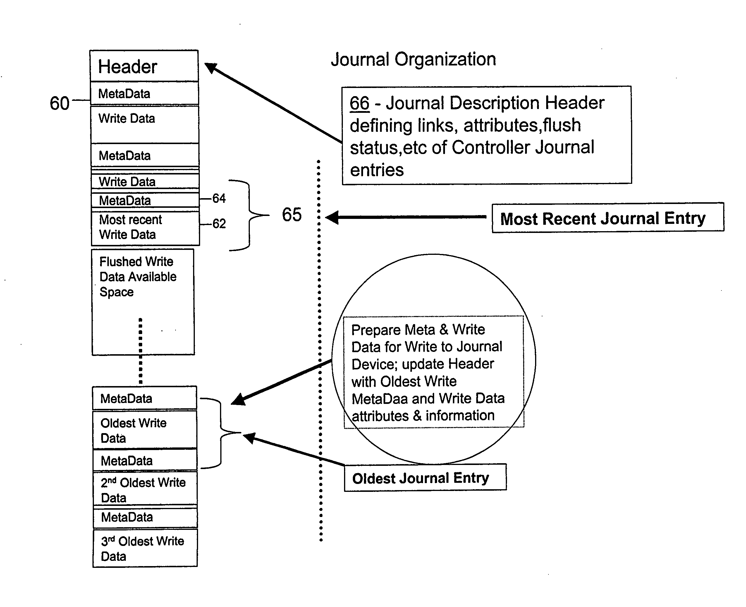
[0069]In accordance with the present invention, an exemplary embodiment thereof is herein set forth. Diagrams are provided below in accompanying figures which show certain preferred embodiments of the present invention as described herein. The specifics and content of a Journal Entry are not germane to limiting the scope of the present invention, but are merely presented as an exemplary embodiment, which is not limiting unless specifically referenced in the claims. Hence, one skilled in the art may adopt other forms of Journal Entry yet not depart from the scope and spirit of the present invention unless so excluded by specific claim language.

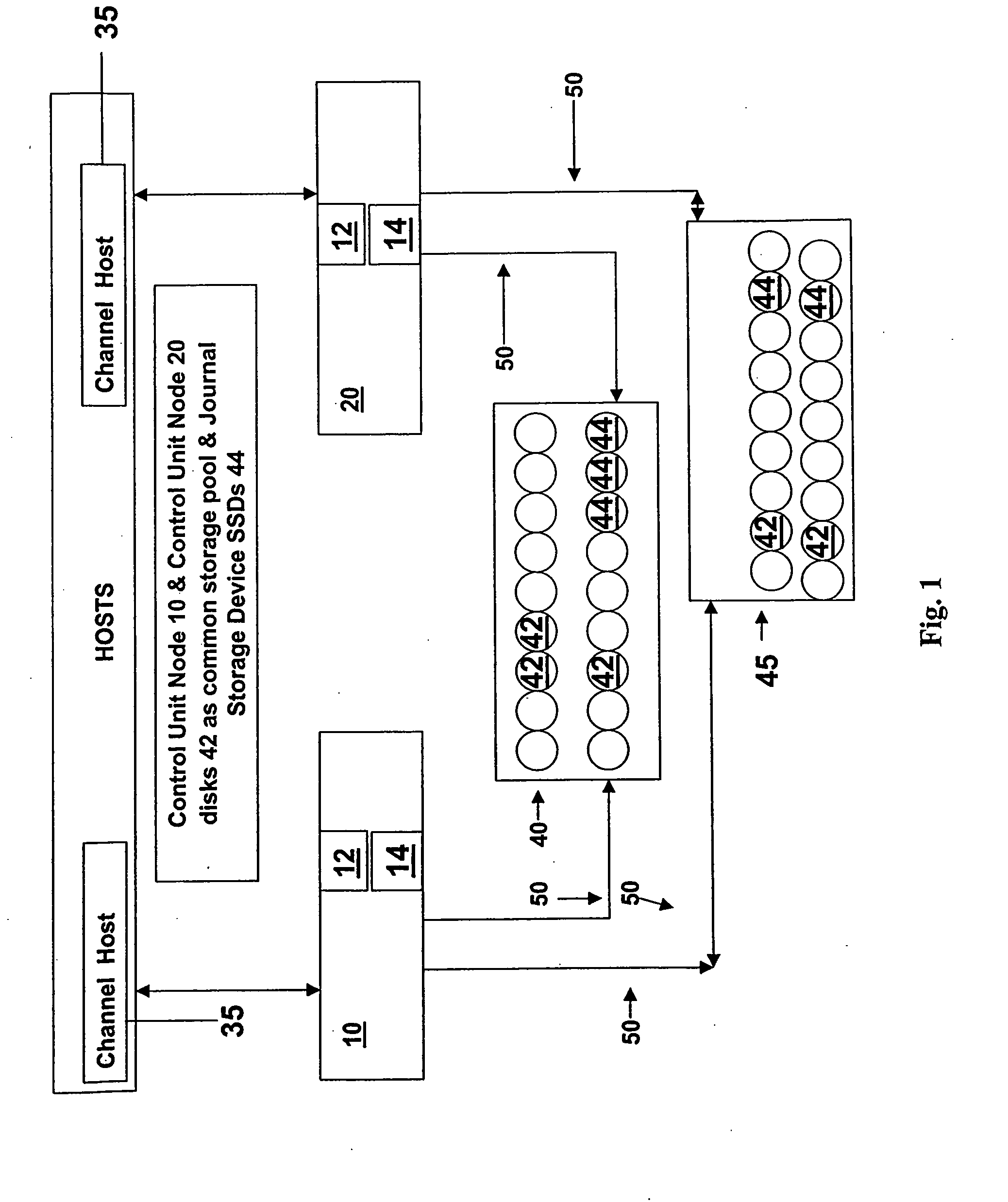
[0070]Referring to FIG. 1, control units 10 and 20 each include a CPU 12 and memory 14 for effecting control unit operation. The memory 14 is shown as a single unit but may be divided into separate partitions accessible by the CPU 12. Included in the memory 14 is a cache memory for storing WRITE DATA, READ DATA and meta-data associated with req...


PUM


Abstract

A “Logging” method and apparatus is provided to protect control unit cached data not yet written to backing storage disk drives. This recording mechanism will copy “WRITE DATA” to a log at a target logically or physically external (to the storage controllers) location equally common to all members of the set of distributed storage control units managing a common storage pool. Upon the failure of one the members of the set of control units, the “Log” information is available to insure that pending “write” data is written to the proper location on the disk drives upon a recovery action. One of the surviving members of the set assumes control of the storage managed by the failing unit by utilizing the recorded information to insure that data not written to backing storage (disks) up to the point of failure is then written to the disk backing storage. The surviving member of the set recovering the failing control unit storage (disk set) ownership will thereby “flush” (WRITE) the Journaled WRITE DATA to the backing storage disk drives before allowing normal operations to proceed.

Description

RELATED APPLICATION[0001]This non-provisional patent application claims priority to provisional application Ser. No. 60 / 961,967, filed Jul. 25, 2007, and incorporates by reference said application.BACKGROUND INFORMATION [0002]A storage control unit has a role of providing control and connection management of an aggregation of disks to client computing systems. The storage control unit is able to identify and parse out the required amount of storage capacity to a given client computer via some administrative interface.[0003]Client computer systems handle write data at file level via a file system implemented by the client computer systems. Using the file system and structure client computers may employ a cache system for storing write data at file level prior to converting to block level addresses and writing the data to backing storage disks. Such cache systems secure data and are sometimes employed to provide for data comparison and integrity verification and are tightly integrated...

Claims


Application Information

Patent Timeline
Patent Type & Authority Applications(United States)
IPC IPC(8): G06F12/08
CPCG06F11/1441G06F12/0866G06F12/0804G06F11/2092
Inventor WILLIS, KENNETH LEWISDUCHESNE, RAYMOND
Owner DIGI DATA CORP
Why Eureka
Try Eureka