
Micro-structured drying for inkjet printers

Inactive Publication Date: 2009-02-05
EASTMAN KODAK CO
View PDF98 Cites 108 Cited by
  • Summary
  • Abstract
  • Description
  • Claims
  • Application Information

AI Technical Summary

Benefits of technology

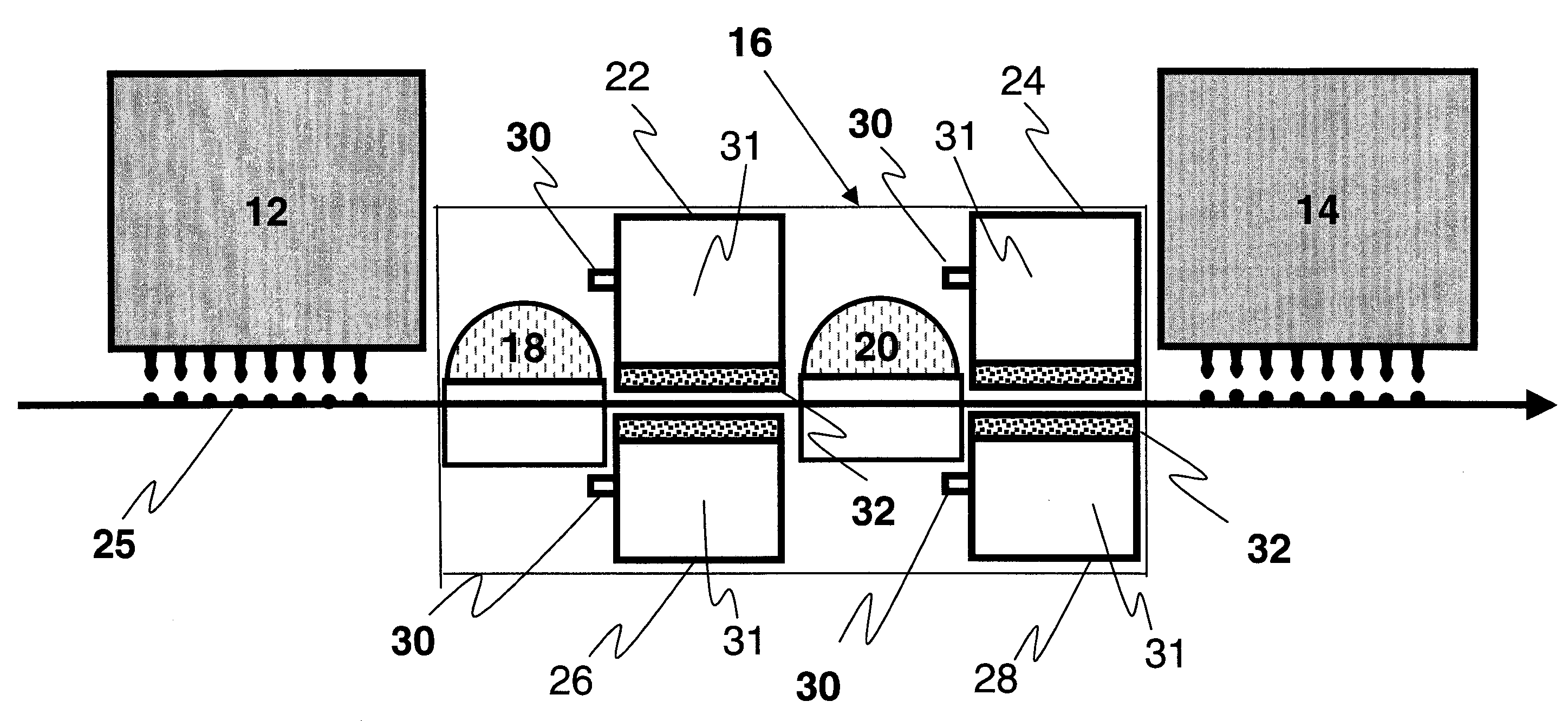
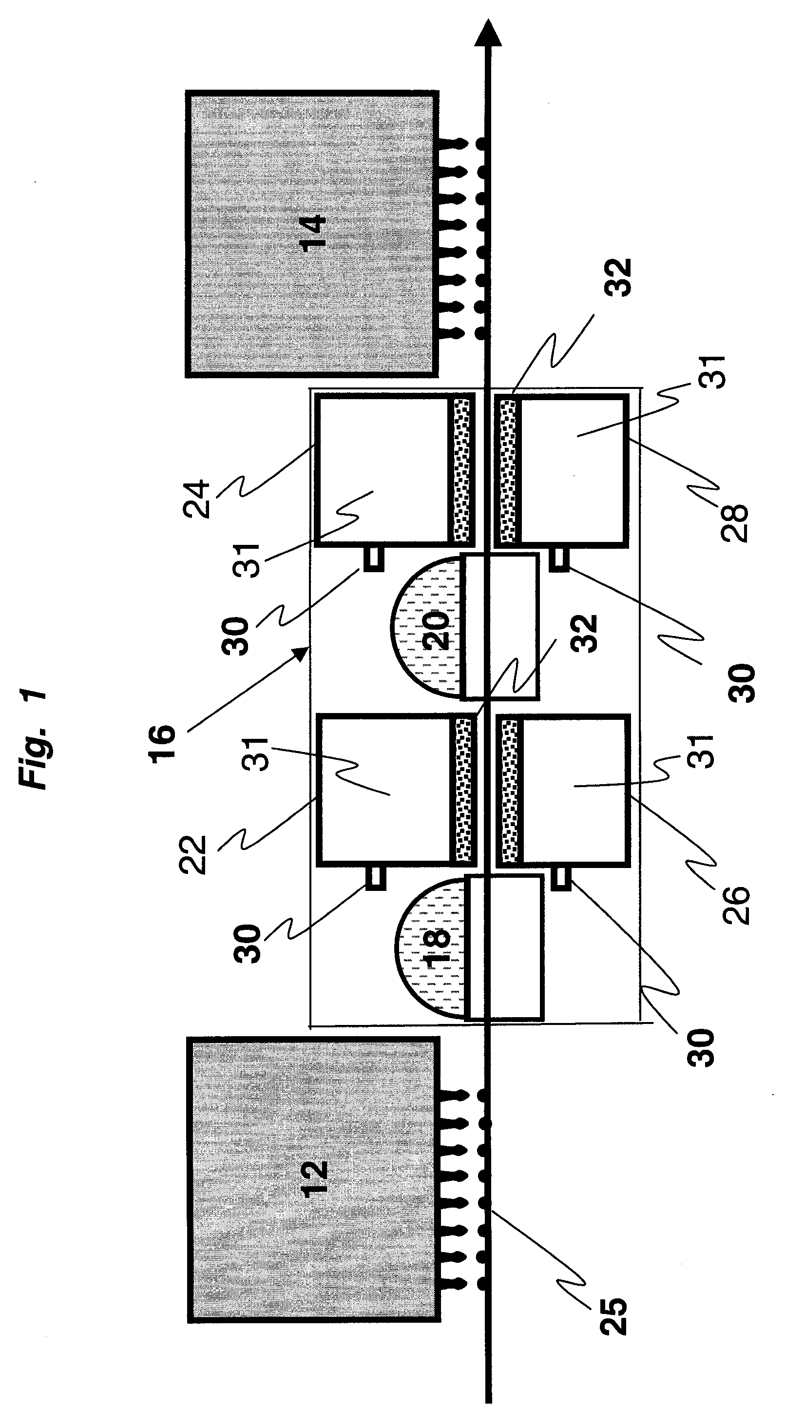
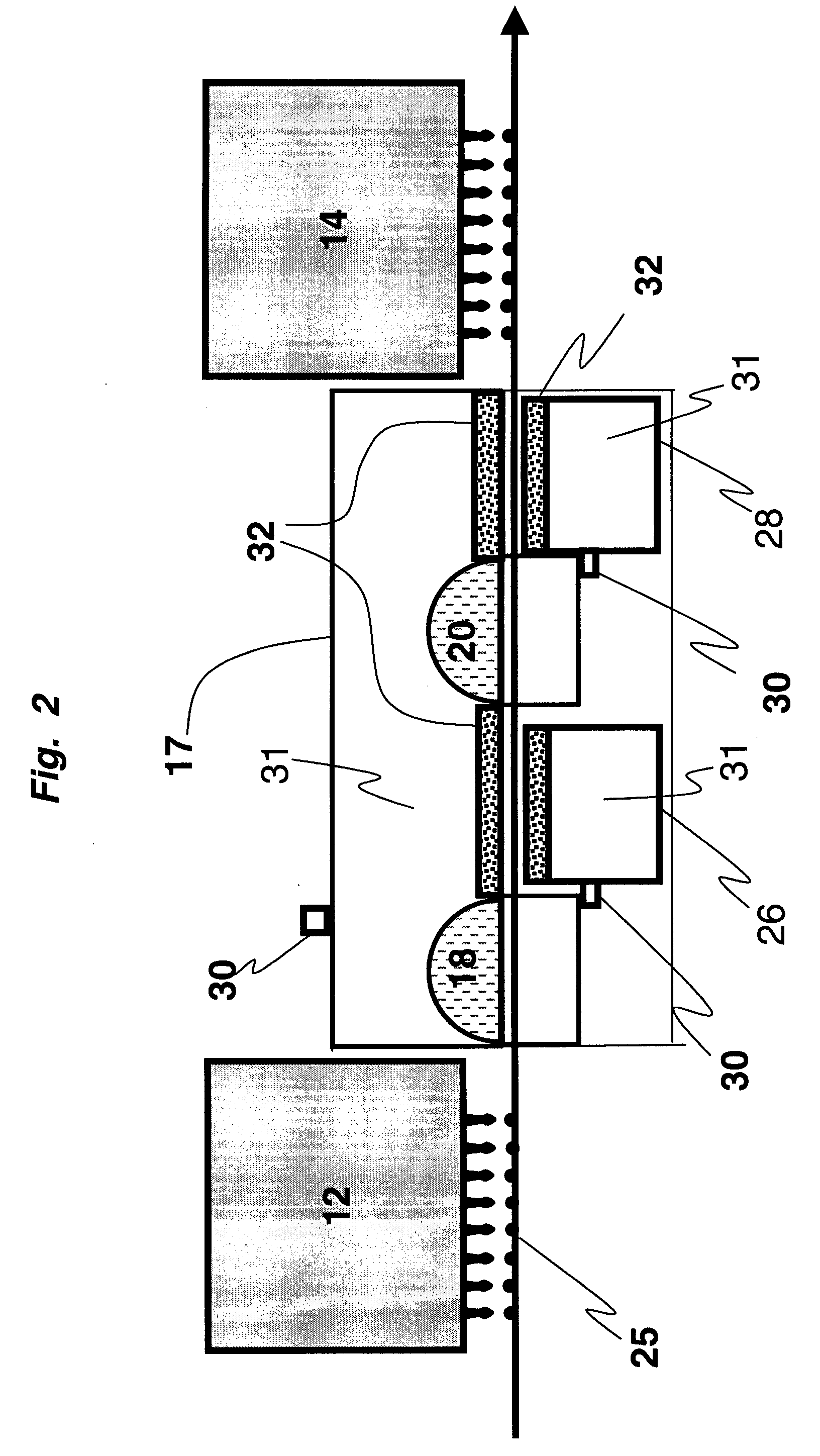
[0013]According to a feature of the present invention, a dryer operable in close proximity to and in series with a water based liquid applicator such as, for example, an inkjet printhead comprises a heat source and an air bearing structure on one side of the predetermined path and having a pressurized air inlet and an air outlet adjacent to the drying position of the receiver medium. Air flow from the air bearing structure outlet forms an air bearing for the receiver medium. A microporous filter is positioned at the outlet and is adapted to convert the air flow from the outlet to a diffuse flow, the microporous filter being formed of an inner layer of very fine screen for optimum air diffusion and an outer layer of courser woven screen to add rigidity and protection from scuffing.
[0014]According to a preferred feature of the present invention, the heat source is radiative and is adapted to selectively heat the water based liquid rather than the receiver medium. The microporous filter is a stainless steel laminate microstructure According to another preferred feature of the present invention a second air bearing structure is provided having an outlet adjacent to the drying position on a side of the predetermined path opposed to the one side, wherein positive pressure is applied onto a first side of the receiver medium by the first-mentioned air bearing structure and onto a second side of the receiver medium by the second air bearing structure to create a contact-less support for the receiver media.

Problems solved by technology

Drop-on-demand systems are generally lower cost but relatively low print speed when compared to continuous systems.
However, continuous ink jet systems employ low viscosity solutions of dyes or pigments in a water solvent, and the printed colors tend to not be as vibrant and dense as with other printing systems.
However, this process also increases the amount water solvent applied to, and absorbed by, the paper.
However, tests have shown that dryers consisting of infrared lamps or microwave radiation cause a significant amount of receiver media heating to occur.
However, selective heating of the ink may create a saturated boundary layer at the ink surface.
While Coanda type or air bar types of air bearings are effective to handle large air volumes and velocities, the air flow is directed toward a common point, which causes a wet image to smear at the air impingement point.

Method used


Image

  • Micro-structured drying for inkjet printers
  • Micro-structured drying for inkjet printers
  • Micro-structured drying for inkjet printers

Examples


Embodiment Construction

[0024]The present description will be directed in particular to elements forming part of, or cooperating more directly with, apparatus in accordance with the present invention. It is to be understood that elements not specifically shown or described may take various forms well known to those skilled in the art.

[0025]Referring now to FIG. 1, a first printhead 12 and a second printhead 14 are separated by an inter-station dryer 16. While the preferred applications of the present invention are for use in drying of inkjet inks on print media, the dryers could also be useful for drying other coatings on paper and other media. The dryer illustrated is a combination of radiation sources 18 and 20. Radiation sources 18 and 20 may be any source of radiation that selectively dries only the fluid ink without sufficiently increasing the temperature of a receiver medium 25, such as for example near infrared lamps, microwaves, infrared radiation, etc. The two radiation sources 18 and 20 are follo...


PUM

PropertyMeasurementUnit
Pressureaaaaaaaaaa
Microstructureaaaaaaaaaa
Transparencyaaaaaaaaaa

Abstract

A dryer operable in close proximity to and in series with an inkjet printhead comprises a heat source and an air bearing structure on one side of the predetermined path and having a pressurized air inlet and an air outlet adjacent to the drying position of the receiver medium. Air flow from the air bearing structure outlet forms an air bearing for the receiver medium. A microporous filter positioned at the outlet and being adapted to convert the air flow from the outlet to a diffuse flow, the microporous filter being formed of an inner layer of very fine screen for optimum air diffusion and an outer layer of courser woven screen to add rigidity and protection from scuffing.

Description

FIELD OF THE INVENTION[0001]The present invention is related to the field of inkjet printers, and more particularly to the drying of the ink during the printing process.BACKGROUND OF THE INVENTION[0002]Inkjet printing is prominent because of its non-impact, low-noise characteristic, its use of plain paper, and its avoidance of toner transfers and fixing. Inkjet printing mechanisms can be categorized as either continuous or drop-on-demand. Drop-on-demand systems are generally lower cost but relatively low print speed when compared to continuous systems. In either drop-on-demand or continuous inkjet systems, it is necessary to assign a different fluid ink color to a separate printhead. Therefore, in color prints, several layers of wet ink may be deposited onto a printed medium.[0003]Traditional printing presses are able to use high viscosity inks to obtain vibrant, high-density colors. However, continuous ink jet systems employ low viscosity solutions of dyes or pigments in a water so...

Claims


Application Information

Patent Timeline
IPC IPC(8): F26B21/06
CPCB41J11/002F26B13/104F26B3/28B41J11/00216B41J11/00222
Inventor PIATT, MICHAEL J.HIX, KENNETH E.GELBART, DANIEL
Owner EASTMAN KODAK CO
Learn More