Plastic fenestration product

a technology of fenestration products and plastics, applied in the field of fenestration products, can solve the problems of affecting the quality of fenestration products, etc., and achieves the effects of reducing the risk of toxicity, reducing the use of fenestration products, and reducing the use ra

Inactive Publication Date: 2009-02-05
NEMAZI JOHN E +1
View PDF47 Cites 10 Cited by
  • Summary
  • Abstract
  • Description
  • Claims
  • Application Information

AI Technical Summary

Benefits of technology

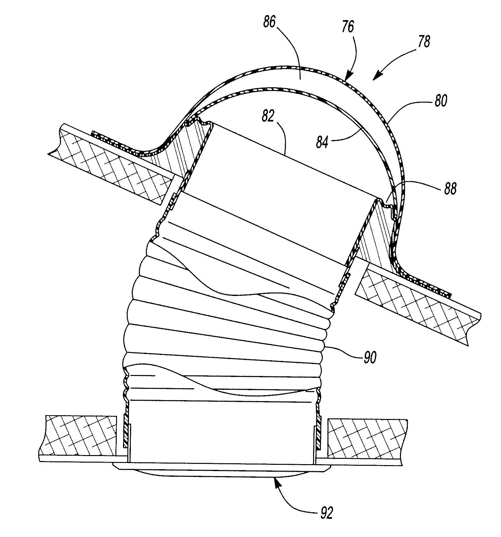
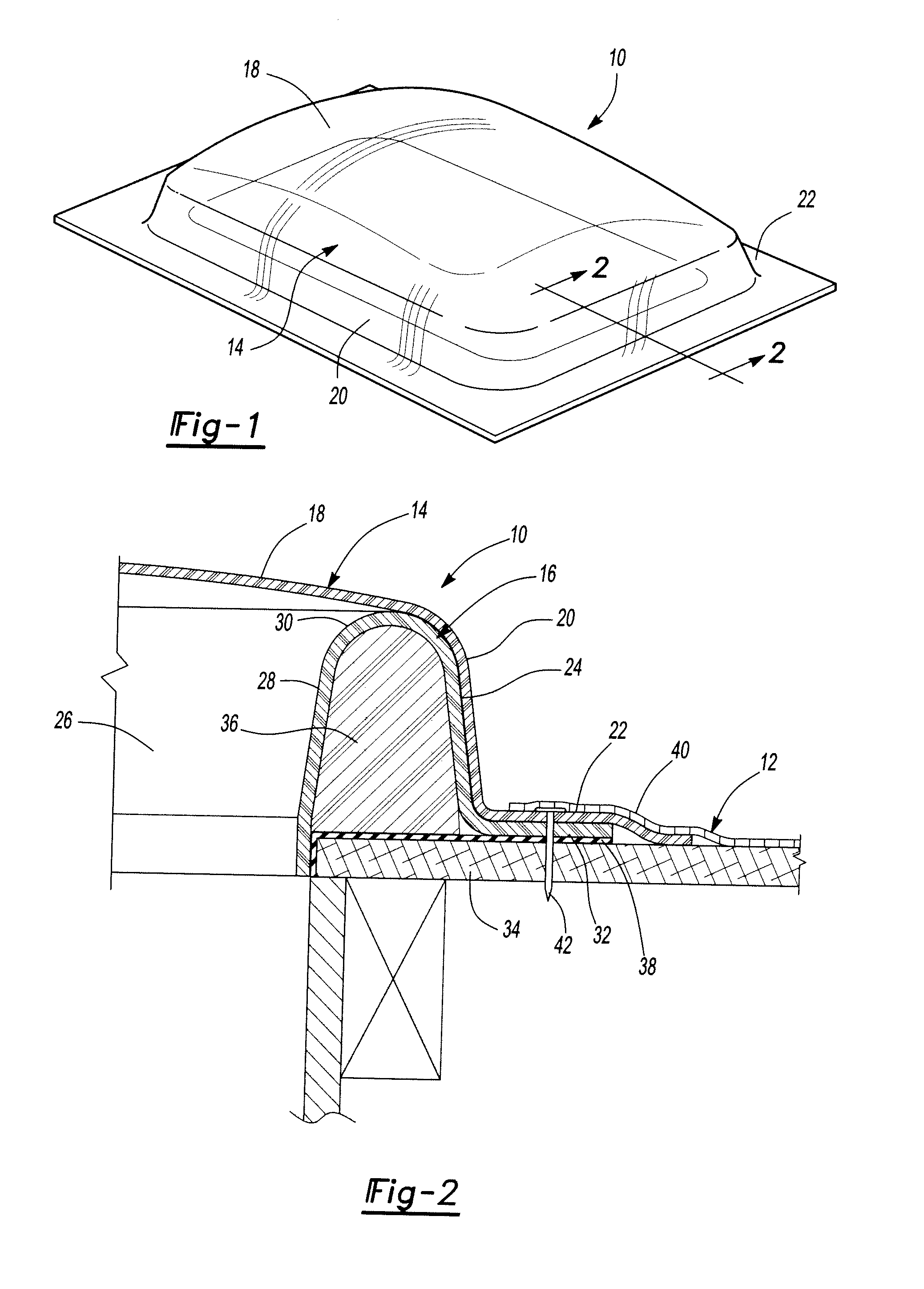
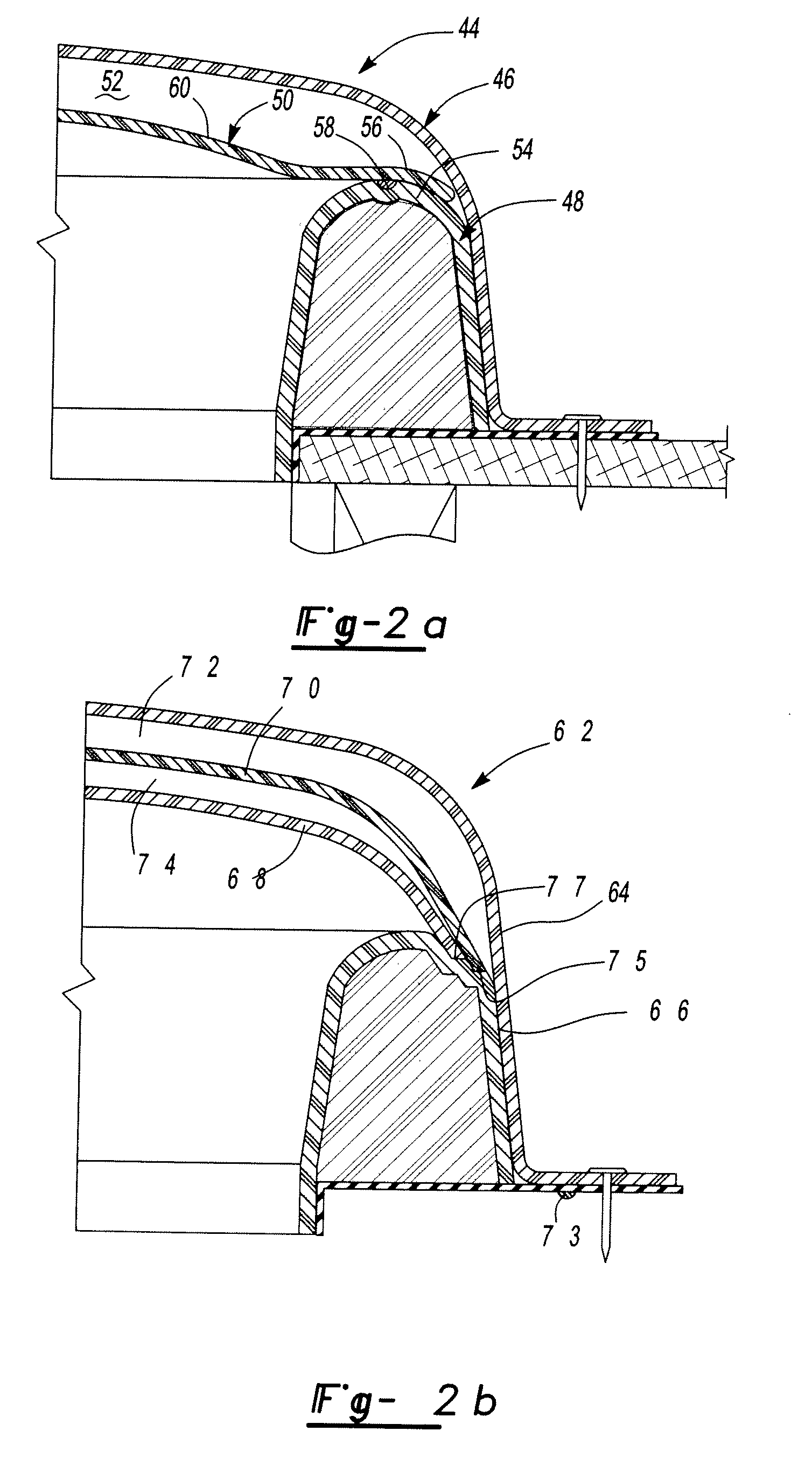
[0008]The fenestration product made in accordance with an embodiment of the present invention includes two main components; a frame and a plastic dome formed of a transparent material which is mounted to the frame. The dome has a central region which transmits visible light and a downwardly extending peripheral edge which extends about the peripheral wall of the frame. The dome is further provided with an outwardly extending flashing flange for mounting the assembly to a wall of a building structure surrounding a building opening.
[0009]In one embodiment of the invention, the frame comprises the unitary plastic ring having a central opening formed therein. The frame peripheral wall is preferably formed of an inverted “U” shape cross-section having an outer peripheral wall cooperating with the plastic dome and an inner peripheral wall aligned with the building opening upon whi

Problems solved by technology

Glass, however, is relatively heavy, susceptible to catastrophic failure and can be difficult to handle and fabricate.
Many plastics, however, are susceptible to scratching, lose their physical properties with age or exposure to environmental factors, and can be relatively expensive.
Many of the mounting systems are comprised of multiple component par

Method used


Image

  • Plastic fenestration product
  • Plastic fenestration product
  • Plastic fenestration product

Examples


Embodiment Construction

)

[0021]As required, detailed embodiments of the present invention are disclosed herein; however, it is to be understood that the disclosed embodiments are merely exemplary of the invention that may be embodied in various and alternative forms. The figures are not necessarily to scale; some features may be exaggerated or minimized to show details of particular components. Therefore, specific structural and functional details disclosed herein are not to be interpreted as limiting, but merely as a representative basis for the claims and / or as a representative basis for teaching one skilled in the art to utilize the present invention.

[0022]Except where expressly indicated, all numerical quantities in this description indicating the amounts of material or conditions are understood as modified by the word “about” in describing the broadest scope of the present invention. Practice within the numerical limits is generally preferred.

[0023]Accordingly, a number of representative examples of t...


PUM


Abstract

A fenestration product such as a skylight or a window assembly is provided having a frame with a peripheral wall with a light transmitting central region and a plastic dome formed of a light transmitting material mounted to the frame. The plastic dome has a central region which transmits light, a downwardly extending peripheral wall extending about and mounted to the peripheral frame, and an outwardly extending flashing flange for mounting the assembly to a building structure. Various embodiments of the part illustrated include a skylight assembly having a frame formed of a plastic layer formed into an inverted “U” shape cross-section forming an annular channel filled with insulating foam. A sealed, vertically mounted window unit is also disclosed. Other embodiments have an insulating layer of transparent plastic material spaced from the dome forming an enclosed, gas filled insulating region. Methods of forming and installing a fenestration assembly are also described.

Description

BACKGROUND OF THE INVENTION[0001]1. Field of the Invention[0002]This invention relates to fenestration products composed primarily of plastic.[0003]2. Background Art[0004]Plastic is used in a variety of fenestration products such as skylights and windows in buildings as an alternative to a glass panel. Plastic and glass fenestration panels each have their respective advantages and disadvantages. Glass is relatively inexpensive, has good optical properties, is scratch resistant and stable in a variety of harsh environments. Glass, however, is relatively heavy, susceptible to catastrophic failure and can be difficult to handle and fabricate. There is a wide a variety of plastics available for use in fenestration products. Some are low cost, tough, readily formable and environmentally stable. Many plastics, however, are susceptible to scratching, lose their physical properties with age or exposure to environmental factors, and can be relatively expensive.[0005]The use of plastic and fe...

Claims


Application Information

Patent Timeline
IPC IPC(8): E04D13/03
CPCE04D13/0315E06B5/02E06B1/6061E04D2013/0345
Inventor NEMAZI, JOHN E.TEMPLETON, G. DANIEL
Owner NEMAZI JOHN E
Why Eureka
Try Eureka