Compound Transmission

a transmission and compound technology, applied in the direction of shafts, couplings, combustion process measures, etc., can solve the problems of high cost, large torsion vibration, complex design of föttinger couplings, etc., and achieve the effect of reducing torsion vibration

Inactive Publication Date: 2009-02-05
SCHAEFFLER TECH AG & CO KG
View PDF46 Cites 6 Cited by
  • Summary
  • Abstract
  • Description
  • Claims
  • Application Information

AI Technical Summary

Benefits of technology

[0006]The object of the invention is therefore to provide a composite drive which both minimizes torsion vibrations and is economical.
[0009]In a Föttinger coupling, the rotational coupling from the pump side to the turbine side takes place by means of the hydrodynamic principle. That also makes it possible to eliminate torsional vibrations—at least partially. Since because of the hydrodynamic principle no rotationally fixed connection exists within the Föttinger coupling, the rotational speeds can fluctuate between the pump side and the turbine side without the transmission of torque being disrupted.

Problems solved by technology

Otherwise a rigid power train of the composite drive would convey non-uniformities of rotation of the crankshaft all the way to the power turbine, which would lead to significant torsion vibration problems.
The design of a Föttinger coupling is very complex, which also makes this solution very costly.
Furthermore, the efficiency is not optimal, due to the slippage inherent in the system.

Method used


Image

  • Compound Transmission
  • Compound Transmission
  • Compound Transmission

Examples


Embodiment Construction

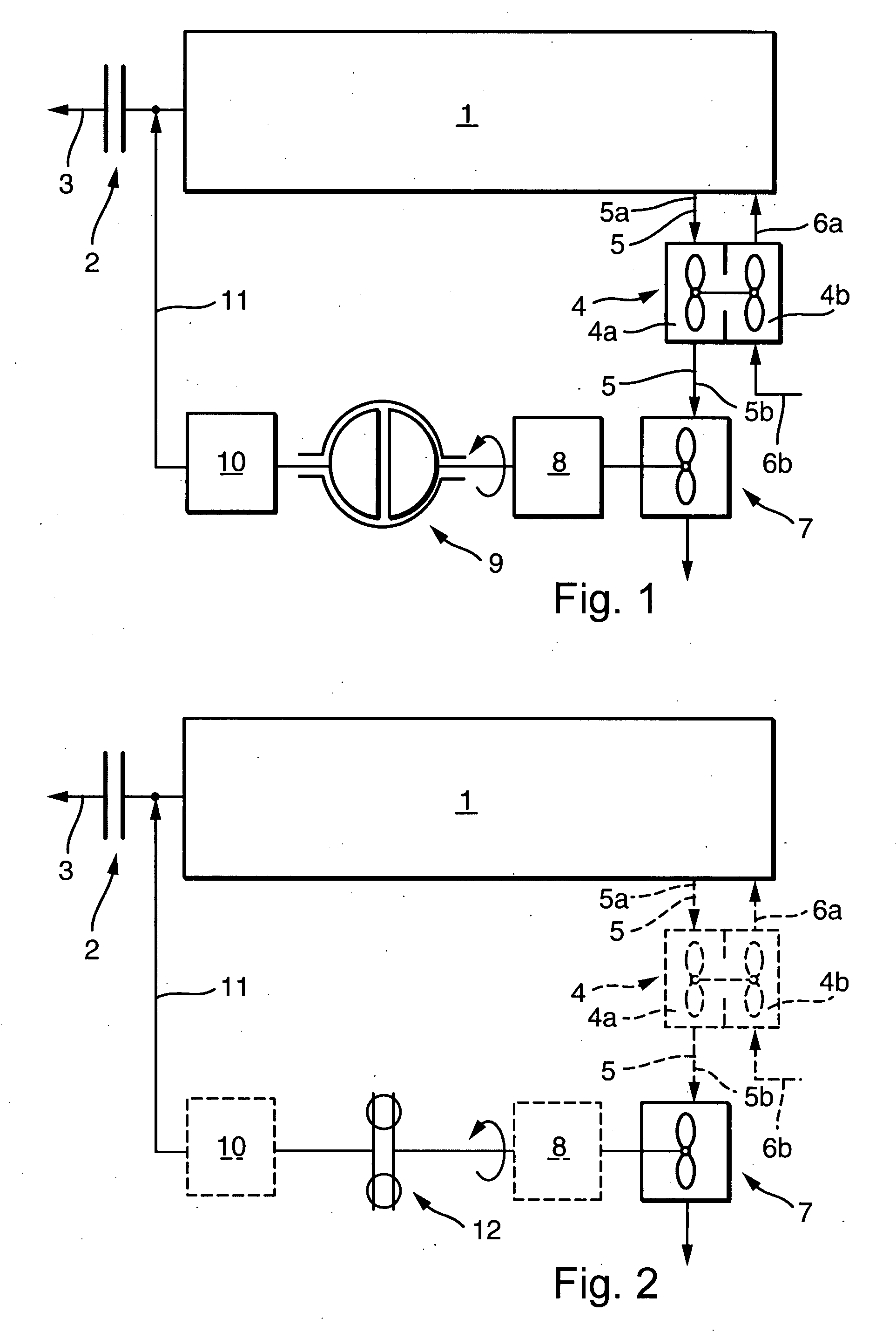
[0018]In FIG. 1, a combustion engine 1 is connected to a turbocharger 4 through an exhaust gasoline 5a. Turbocharger 4 is subdivided into the exhaust gas turbine 4a and the charge air turbine 4b. During operation of turbocharger 4, a charge air stream 6b passes through charge air turbine 4b and becomes charge air stream 6a, which is blown into combustion engine 1.

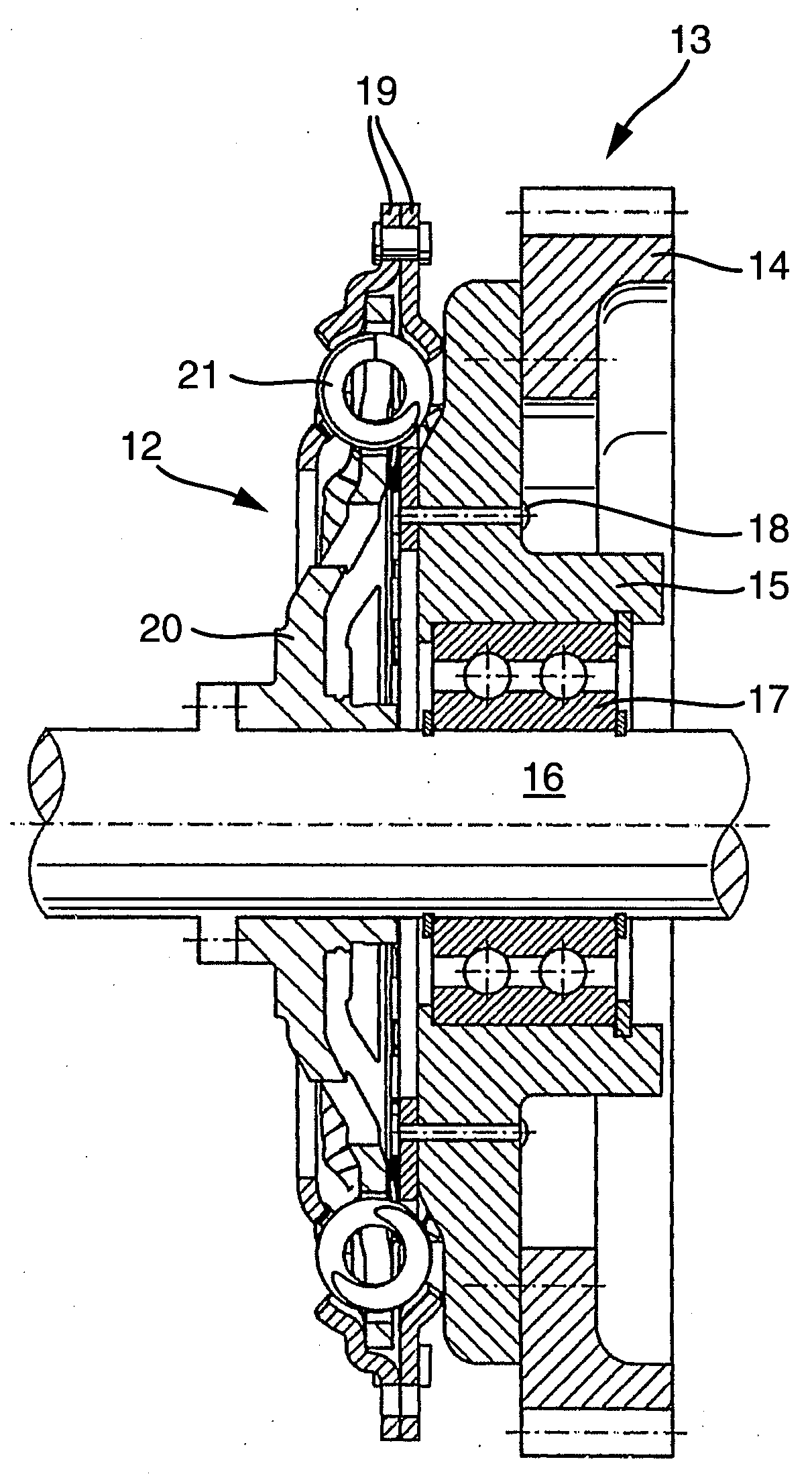
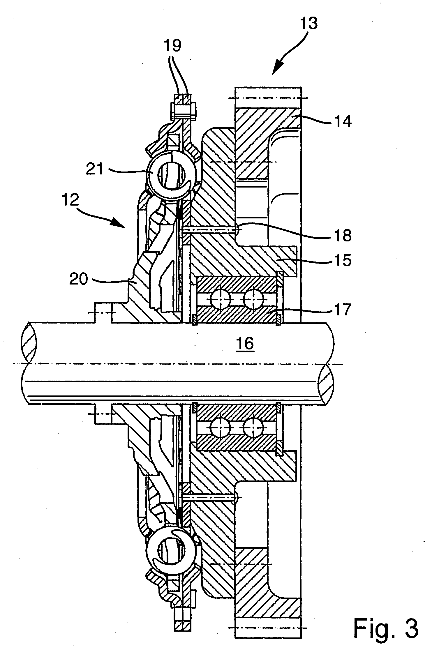
[0019]Farther along in exhaust gas line 5 is exhaust gas line 5b, which is flow-connected to a compound drive turbine 7. A second yield is obtained here from the exhaust air, the intent here being to obtain rotational energy for the compound drive. Compound drive turbine 7 is connected to a reduction gear by a rotationally fixed connection. The intent of this reduction gear 8 is to reduce the high speed of the compound drive turbine 7 to the nominal speed of the down-line Föttinger coupling 9. The right side of Föttinger coupling 9 here is the pump, while the left half shell of the Föttinger coupling embodies the turbine. A...


PUM


Abstract

An internal combustion engine comprises a turbo-compound and the known Föttinger-coupling is replaced by a torsion vibration damper. The Föttinger-coupling, which is used to transmit power, has high losses in power when it is necessary to have a differential rotational speed between the input side and the output side, i.e., the appearance of a slip. The losses are not used in a torsion vibration damper which has at least the same quality as a Föttinger-coupling.

Description

CROSS REFERENCE TO RELATED APPLICATIONS[0001]This application claims the benefit of International Application PCT / DE2006 / 000519, filed 24 Mar. 2006, which claims priority from German Application DE 10 2005 014 000.9, filed 26 Mar. 2005, said applications are incorporated-by-reference herein.FIELD OF THE INVENTION[0002]The invention relates to a compound drive in combination with a combustion engine.BACKGROUND OF THE INVENTION[0003]Compound drives are also called turbo-compounds. In such compound drives, the stream of exhaust gas from a combustion engine—in many cases a diesel engine—is routed through the exhaust gas turbine of a turbocharger. The charge air is fed to the combustion engine through a blower that is connected to the exhaust gas turbine with a rotationally fixed connection. As the exhaust gases continue on their way, in the existing art—in combination with a compound drive—they pass through a second turbine. This second turbine may transmit its rotational energy to a re...

Claims


Application Information

Patent Timeline
Patent Type & Authority Applications(United States)
IPC IPC(8): F02G5/02F02B41/10F16F15/12
CPCF02B41/10F02B2700/026Y02T10/163F16D3/12F16F15/123F02B2720/128Y02T10/12
Inventor SCHENCK, KAI SEBASTIANREIK, WOLFGANGMULLER, BRUNO
Owner SCHAEFFLER TECH AG & CO KG
Why Eureka
Try Eureka