
Plate washing system with ultrasonic cleaning of pipes and a control method thereof

a technology of plate washing system and ultrasonic cleaning, which is applied in the direction of cleaning using liquids, instruments, laboratories, etc., can solve the problems of not always the case, material residues can affect the performance of pipes, even render pipes inoperable, and the impact of performance issues is currently not detectabl

Active Publication Date: 2009-02-05
AGILENT TECH INC
View PDF10 Cites 34 Cited by
  • Summary
  • Abstract
  • Description
  • Claims
  • Application Information

AI Technical Summary

Benefits of technology

[0017]According to another aspect of the invention, a plate washing system includes at least one manifold having a plurality of pipes configured to be provided with wells of a plate in order to wash the wells; a tank that is capable of being filled with a fluid; an ultr...

Problems solved by technology

However, this is not always the case.
However, as a result of evaporation, the dispensed materials leave solid materials (such as salts from the assay reagents) within the pipes.
The solid material residue can impact the performance of the pipes or even render the pipes inoperable.
Impact on performance issues is currently not detectable within the microplate washing system and requires external instrumentation to detect volumetric dispense and aspiration errors.
Although the use of ultrasonic cleaning is effective, ultrasonic cleaning using a commercially available tank is a complex process.

Method used


Image

  • Plate washing system with ultrasonic cleaning of pipes and a control method thereof
  • Plate washing system with ultrasonic cleaning of pipes and a control method thereof
  • Plate washing system with ultrasonic cleaning of pipes and a control method thereof

Examples


Embodiment Construction

[0027]While the invention is open to various modifications and alternative forms, specific embodiments thereof are shown by way of examples in the drawings and are described herein in detail. There is no intent to limit the invention to the particular forms disclosed.

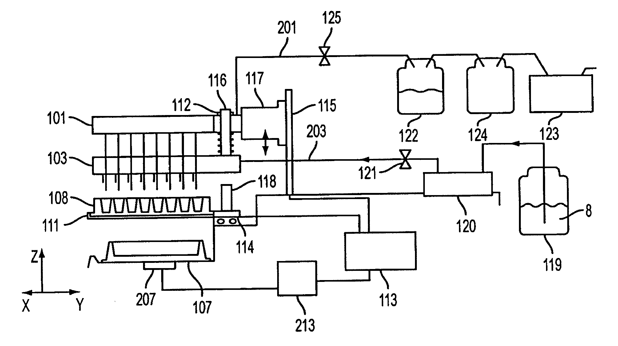
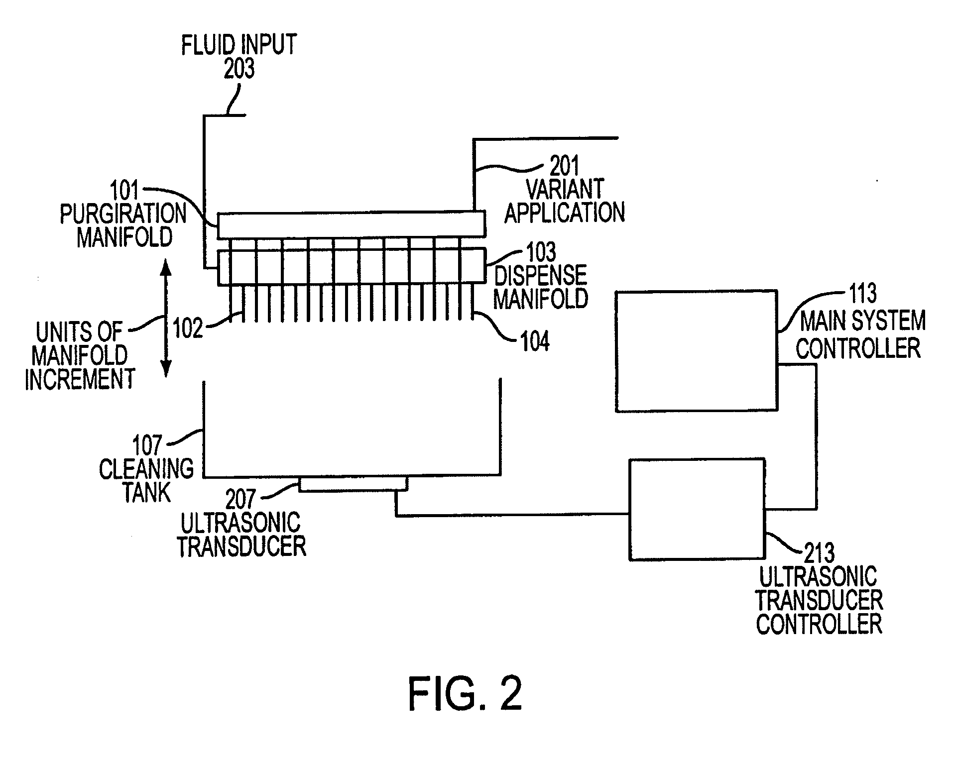
[0028]FIG. 2 generally shows a first non-limiting embodiment of an ultrasonic cleaning system of a plate washing system. The ultrasonic cleaning system includes a dispense manifold 103 having dispense pipes 102, an aspiration manifold 101 having aspirate pipes 104, a fluid input line 203, a vacuum aspiration line 201, a cleaning tank 107, and an ultrasonic transducer 207 mounted on the tank 107. However, the invention is not limited to separate dispense and aspiration manifolds and a single manifold containing both aspirate and dispense pipes can also be used.

[0029]In order to clean the pipes, the dispense and aspiration manifolds 103, 101 are lowered so that the pipes 102, 104 are within the cleaning tank 107. However,...


PUM


Abstract

An automated method of cleaning the pipes of a plate washing system is provided. The plate washing system includes at least one manifold having a plurality of pipes configured to be provided within wells of a plate in order to wash the wells, an ultrasonic transducer mounted to a tank, and a control system. The plate washing system also includes sensors to sense the position of the pipes relative to plate and the tank, and the fluid level within the wells of the plate. The method includes dispensing fluid to the tank, submerging the tips of the pipes within the fluid, activating the ultrasonic transducer in order to vibrate the fluid, and aspirating the fluid from the tank. The control system may initiate a cleaning operation at the request of the user, at a scheduled interval, or when the level sensing system detects a decrease in instrument function.

Description

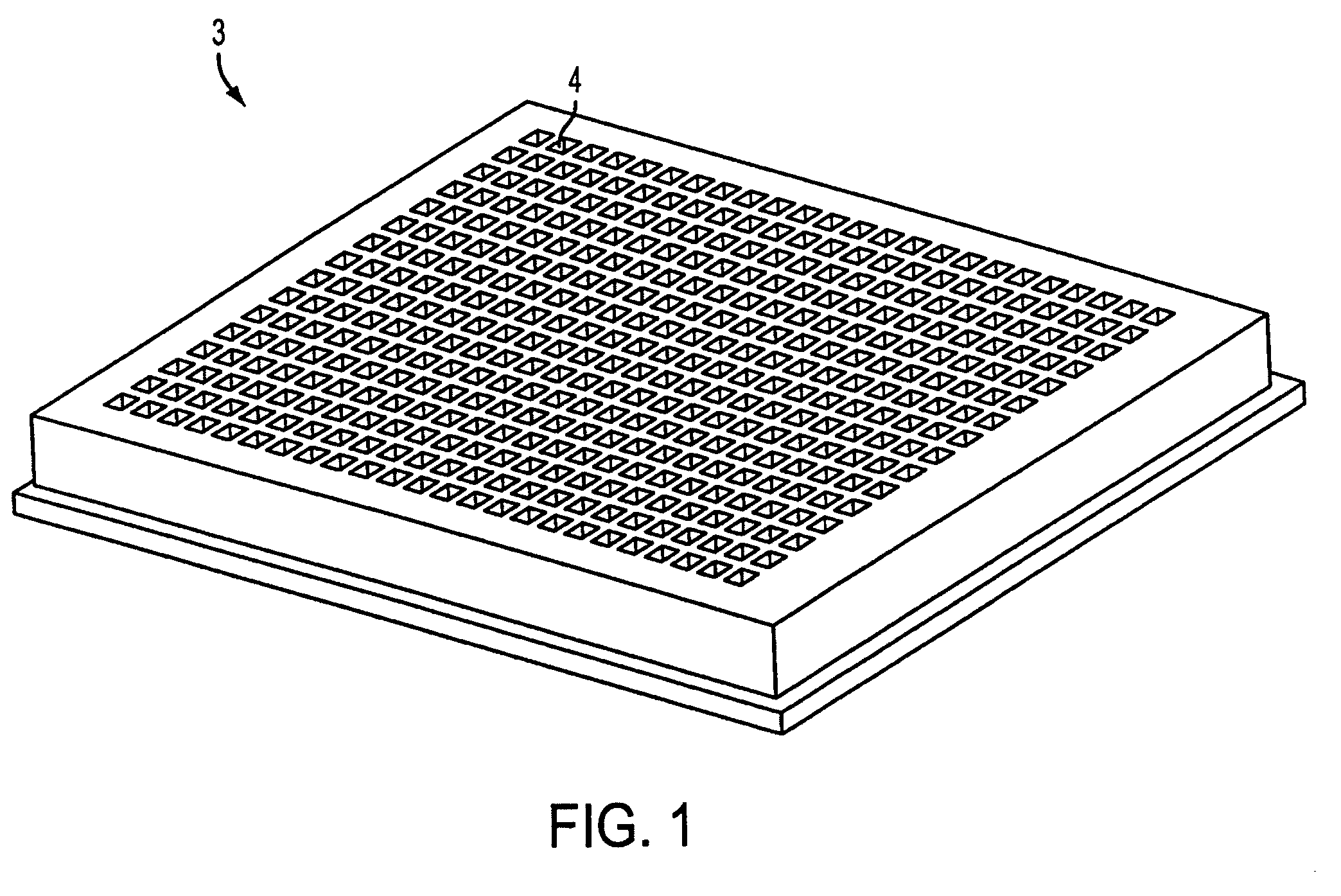
CROSS-REFERENCE TO RELATED APPLICATIONS[0001]This application is a Continuation-In-Part application of U.S. application Ser. No. 11 / 183,867, filed on Jul. 19, 2005, which is a Continuation-In-Part application of U.S. application Ser. No. 10 / 939,467, filed on Sep. 14, 2004. The entire disclosures of U.S. application Ser. Nos. 11 / 183,867 and 10 / 939,467 are incorporated herein by reference.BACKGROUND OF THE INVENTION[0002]1. Technical Field[0003]This invention generally relates to a plate washing system with ultrasonic cleaning of pipes and a control method thereof. The ultrasonic cleaning system can provide cleaning of the plate washing system's dispense and aspirate pipes, and monitor the performance in terms of volumetric accuracy and precision.[0004]2. Discussion of Related Art[0005]Certain laboratory operations, such as immuno assays, require the testing of small samples which are carried out in an arrangement of microwells having volumes of, for example 50-300 microliters or less...

Claims


Application Information

Patent Timeline
IPC IPC(8): B08B3/12B08B7/04B08B9/00
CPCB01L2200/143B01L2300/0829B01L2300/0864B01L2400/0439B01L2400/0487B01L99/00B08B3/12B08B9/00B08B2209/005G01N35/1004G01N2035/00554B08B3/044B01L13/02B01L3/5085
Inventor GIFFORD, ROBERT M.BUEHRER, LENORECLEVELAND, THOMAS A.
Owner AGILENT TECH INC
Learn More