Polymer film splicing method and device, and stretching method

a polymer film and splicing technology, applied in the direction of soldering devices, manufacturing tools, auxilary welding devices, etc., can solve the problems of inability to achieve sufficient splicing strength, inability to stretch the film enough to improve optical properties, and decreased area as a product, so as to facilitate thermal decomposition and prevent the occurrence of wrinkles

Inactive Publication Date: 2009-02-05
FUJIFILM CORP
View PDF3 Cites 11 Cited by
  • Summary
  • Abstract
  • Description
  • Claims
  • Application Information

AI Technical Summary

Benefits of technology

[0011]To solve the above problems, a first object of the present invention is to provide a splicing method and device for more infallibly splicing polymer films by thermal welding even though the polymer film such as cellulose ester...

Problems solved by technology

Therefore, in the case that the stretching speed is adjusted in accordance with the film producing speed, it is impossible to stretch the film enough to improve the optical properties.
Accordingly, there is a problem that it is impossible to achieve sufficient splicing strength.
Therefore, there is a problem that the area as a product is decreased.
Further, in some ca...

Method used


Image

  • Polymer film splicing method and device, and stretching method
  • Polymer film splicing method and device, and stretching method
  • Polymer film splicing method and device, and stretching method

Examples


embodiment 1

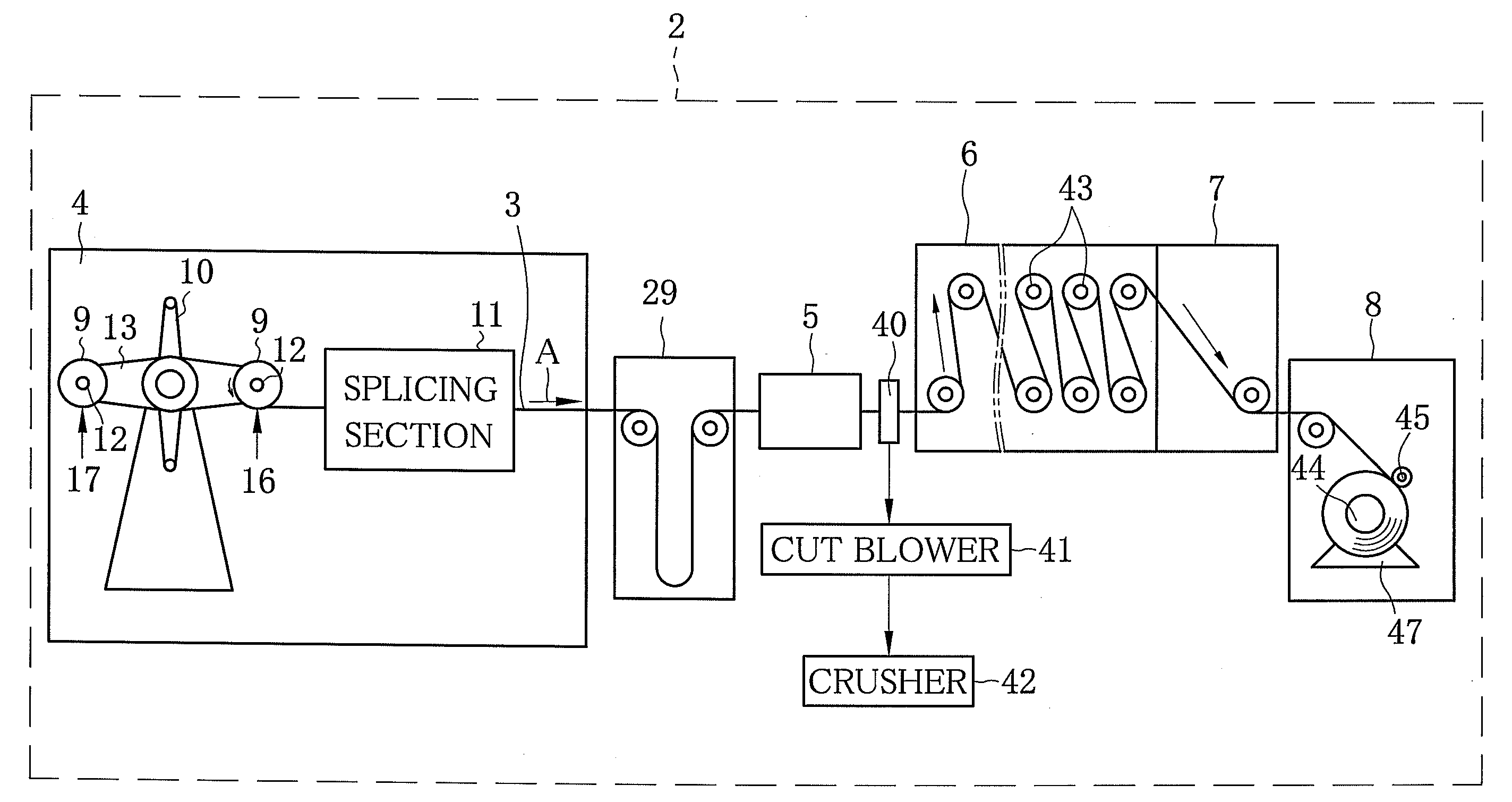
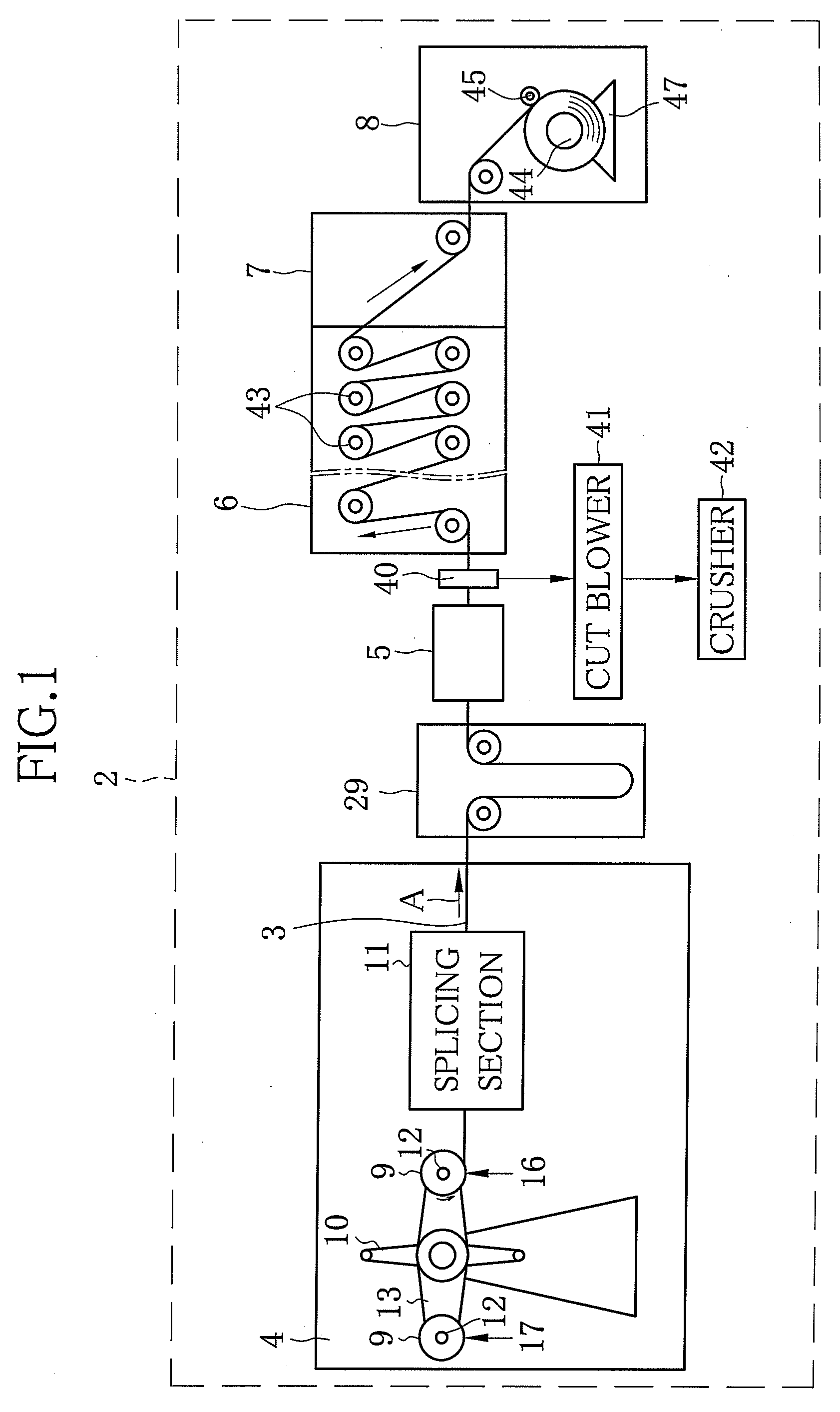
[0033]As shown in FIG. 1, an off-line stretching device 2 is used for stretching a TAC film 3 (hereinafter referred to as film 3), and includes a film supply chamber 4, a tenter section 5, a relaxation chamber 6, a cooling chamber 7, and a winding chamber 8 disposed in this order from a upstream side along a film transporting direction A. A film roll 9 produced in a solution casting apparatus is loaded in the film supply chamber 4. The film roll 9 is obtained by winding the film 3 around a core in a roll manner. The film 3 is fed from the film roll 9 loaded in the film supply chamber 4 to the tenter section 5. In the tenter section 5, the film 3 is continuously stretched in a film width direction while being heated. The stretched film 3 passes through the relaxation chamber 6 and the cooling chamber 7 to be cooled. The cooled film 3 is wound in the winding chamber 8. In the tenter section 5, the film 3 is stretched in the film width direction by 100.5% to 300%. In each of the film s...

embodiment 2

[0058]Although the preceding film 3a and the trailing film 3b are spliced to each other with use of the heat sealer 20 in the splicing section 11 in Embodiment 1, alternatively, as shown in FIG. 8, an ultrasonic splicer 50 can be used to splice the preceding film 3a and the trailing film 3b.

[0059]The ultrasonic splicer 50 mechanically vibrates the film 3, for example, 20,000 to 28,000 times / sec at the amplitude of 0.03 mm, to heat and weld the film 3. The ultrasonic splicer 50 includes two transducers 57, a horn 59, and a transmitter 53. A permanent magnet 54 is disposed between the transducers 57. A coil 55 is bridged over each of the transducers 57. The transmitter 53 causes the coil 55 to drive the transducers 57. The transducer 57 converts electrical vibration to mechanical vibration. The horn 59 amplifies the mechanical vibration caused by the transducer 57 to apply energy to the rear end of the preceding film 3a and the front end of the trailing film 3b (vibrate the rear end ...

embodiment 3

[0060]Although the preceding film 3a and the trailing film 3b are spliced to each other with use of the heat sealer 20 in the splicing section 11 in Embodiment 1, alternatively, as shown in FIG. 9, the splicing may be performed with use of acetone as one of the solvents contained in the dope used in forming the TAC film.

[0061]Acetone is applied to the spliced area 28 at the rear end of the preceding film 3a by spraying, and then the front end of the trailing film 3b is put on the rear end of the preceding film 3a. Thereafter, the rear end of the preceding film 3a and the front end of the trailing film 3b are spliced to each other by the acetone in a press-contact manner.


PUM

PropertyMeasurementUnit
Temperatureaaaaaaaaaa
Shrinkageaaaaaaaaaa
Speedaaaaaaaaaa

Abstract

An off-line stretching device includes a film supply chamber, a tenter section, a relaxation chamber, a cooling chamber, and a winding chamber. The film supply chamber includes a splicing section, where a rear end of a preceding film and a front end of a trailing film are overlapped to be spliced to each other by thermal welding. The thermal welding is performed from above and below the film while a temperature of welding heads of a heat sealer, contacting with the film, is kept at a level equal to or less than a decomposition temperature of the preceding and trailing films. The spliced film is stretched in the tenter section and subjected to heat treatment for stress relaxation in the relaxation chamber, to shrink in a film width direction. Since the shrinkage amount of a spliced area and that of a peripheral area become equal to each other, the occurrence of wrinkles in the spliced area and tears of the film in the peripheral area can be prevented. Additionally, since a heat transfer distance between a film surface and a film splicing surface can be shortened, the heating from above and below the film enables high-speed welding.

Description

FIELD OF THE INVENTION[0001]The present invention relates to a polymer film splicing method and device, and a polymer film stretching method.BACKGROUND OF THE INVENTION[0002]Recently, in accordance with rapid development and popularization of liquid crystal display (LCD) or the like, the demand for a cellulose ester (cellulose acylate) film, in particular, a triacetyl cellulose (TAC) film used as a protective film for the LCD or the like, has been increasing. According to the increase in the demand for the TAC film, the improvement in productivity thereof has been desired. The TAC film is produced as follows. A dope containing the TAC and a solvent is cast through a casting die onto a support continuously moving to form a casting film thereon. The casting film is dried or cooled to be solidified. The solidified casting film is peeled from the support to form a wet film. The wet film is dried and wound as a film. According to a solution casting method described above, it is possible ...

Claims


Application Information

Patent Timeline
IPC IPC(8): B29C65/06
CPCB29C55/08B29C66/91645B29C65/08B29C65/18B29C65/38B29C65/4895B29C65/5057B29C66/0342B29C66/1122B29C66/344B29C66/43B29C66/855B29C66/91231B29C66/91421B29C66/919B29C66/91921B29K2001/00B29K2001/12B29C55/20B29C66/91423B29C66/91411B29C66/9141B29C66/81419B29C66/81417B29C66/8322B29C66/83221B29C65/305B29C65/00B29C66/73711B29C66/73715B29C66/71B29C66/853B29K2001/14B29C65/02
Inventor AOSHIMA, SHINSUKE
Owner FUJIFILM CORP
Why Eureka
Try Eureka