Electric disk brake

a technology of electric disk brake and disc brake, which is applied in the direction of mechanically actuated brakes, brake systems, actuators, etc., can solve the problems of brake judder is likely to occur, uneven absorption of disk rotors, etc., and achieve the effect of preventing uneven abrasion of disk rotors

a technology of electric disk brake and disc brake, which is applied in the direction of mechanically actuated brakes, brake systems, actuators, etc., can solve the problems of brake judder is likely to occur, uneven absorption of disk rotors, etc., and achieve the effect of preventing uneven abrasion of disk rotors

US20090032342A1Active Publication Date: 2009-02-05HITACHI ASTEMO LTD

Image

  • Electric disk brake
  • Electric disk brake
  • Electric disk brake

Examples


Embodiment Construction

[0048]Hereinbelow, an embodiment of the present invention will be described in detail with reference to the accompanying drawings.

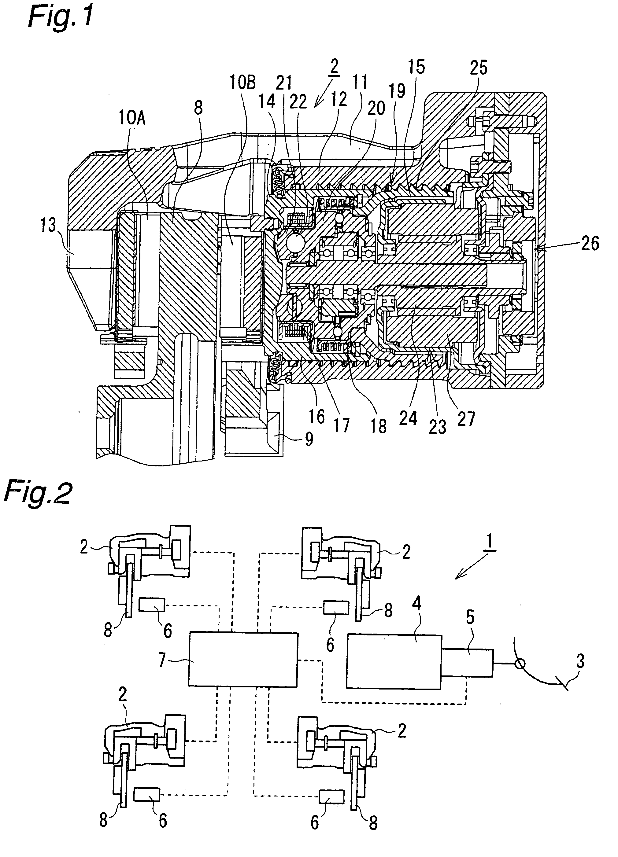
[0049]FIG. 2 schematically illustrates a structure of an electric disk brake of an embodiment of the present invention. As shown in FIG. 2, an electric disk brake 1 comprises an electric disk brake main body 2 mounted on each of wheels of a vehicle, a stroke simulator 4 coupled with a brake pedal 3, a stroke sensor 5 which detects an operation stroke of the brake pedal 3 carried out by a driver, and a controller 7 (controlling means) which supplies a controlling electric current to the electric disk brake main body 2 based on detection results of various sensors such as the stroke sensor 5 and a vehicle speed sensor 6.

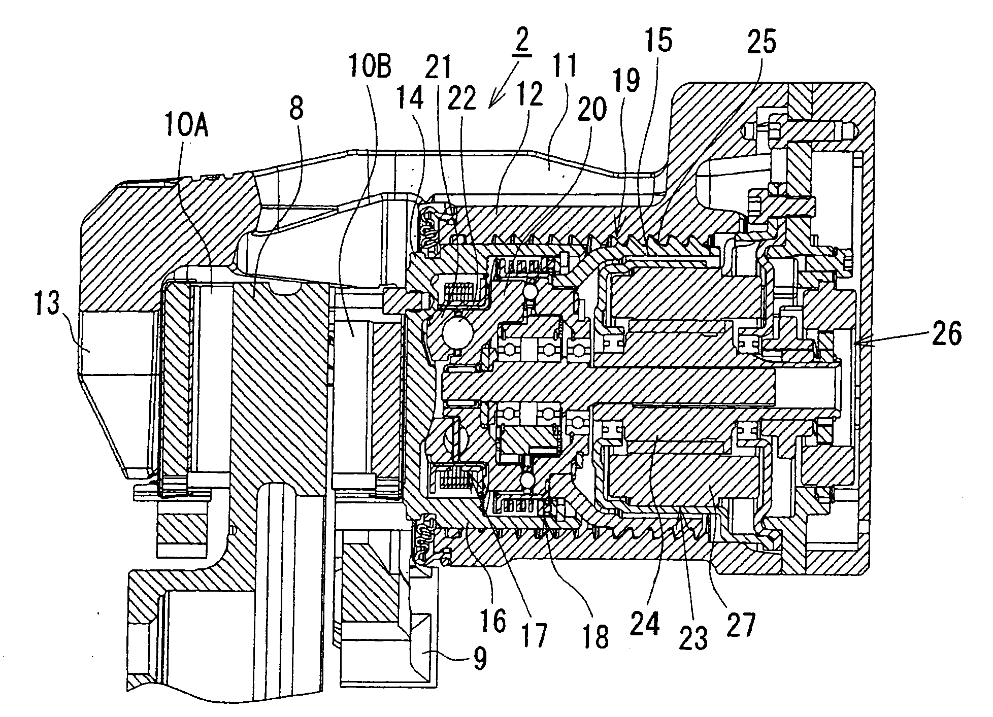
[0050]As shown in FIG. 1, the electric disk brake main body 2 is embodied as a floating caliper type disk brake. The main body 2 comprises a carrier 9, a pair of brake pads 10A and 10B, and caliper main body 11. The carrier 9 is fixed to a n...


PUM


Abstract

An object of the present invention is to, in an electric disk brake, prevent uneven abrasion of a disk rotor due to contact of the disk rotor to a brake pad when brake is not in operation. In the present invention, a rotation of an electric motor is slowed down by a differential speed reducing mechanism, and is converted to a linear motion of a piston by a ball ramp mechanism. Brake pads are pressed against a disk rotor by the piston to generate a brake force. When brake is not in operation, the piton is retracted by a reverse rotation of the electric motor so that a predetermined pad clearance is maintained. When brake is not in operation, a pad-retracting-control electric current is supplied to the electric motor so that the piston is biased backward while being maintained in one position. When brake is not in operation, contact of the disk rotor to the brake pads due to runout of the disk rotor triggers smooth retracting of the piston, whereby uneven abrasion of the disk rotor can be prevented.

Description

BACKGROUND OF THE INVENTION[0001]The present invention relates to an electric disk brake which generates a brake force by pressing a brake pad to a disk rotor by use of an electric motor.[0002]As an electric disk brake, for example, Japanese Patent Public Disclosure 2003-202042 discloses an electric disk brake in which a rotational movement of a rotor of an electric motor is converted into a linear movement of a piston by use of a rotation-linear motion converting mechanism such as a ball screw mechanism or a ball ramp mechanism, and brake pads are pressed against a disk rotor by the piston, thereby generating a brake force. In the electric disk brake, a force of a driver's pressing a brake pedal (or displacement amount) is detected by a sensor, and rotation of the electric motor is controlled by a controller based on the detected value, whereby a desired brake force can be generated.[0003]In this kind of electric disk brake, control accuracy can be improved by appropriate controlli...

Claims


Application Information

Patent Timeline
05 Feb 2009
Publication
US20090032342A1
IPC
F16D55/225
CPC
B60T13/741; F16D65/18; F16D2125/54; F16D2125/36; F16D2125/40; F16D2121/24
Inventors
YAMAGUCHI, TOHMA