Method and System for Charged-Particle Beam Lithography

a technology of charged particles and beams, applied in the field of method and system of charged particle beams, can solve the problems of insufficient accuracy of dose correction, inability to say that the proximity effect and foggy errors are varied, and the magnitude of proximity errors and foggy errors cannot be said to be accurate enough, etc., to achieve the effect of simple processing and sufficient accuracy

Inactive Publication Date: 2009-02-05
JEOL LTD
View PDF10 Cites 16 Cited by
  • Summary
  • Abstract
  • Description
  • Claims
  • Application Information

AI Technical Summary

Benefits of technology

[0011]It is an object of the present invention to provide a method and system for charged-particle b

Problems solved by technology

However, the magnitudes of the proximity effects and foggy errors are varied by shot-to-shot dose variations.
Therefore, if correction doses obtained by estimating each individual effect alone are used, the correction dose results in overdose o

Method used


Image

  • Method and System for Charged-Particle Beam Lithography
  • Method and System for Charged-Particle Beam Lithography
  • Method and System for Charged-Particle Beam Lithography

Examples


Embodiment Construction

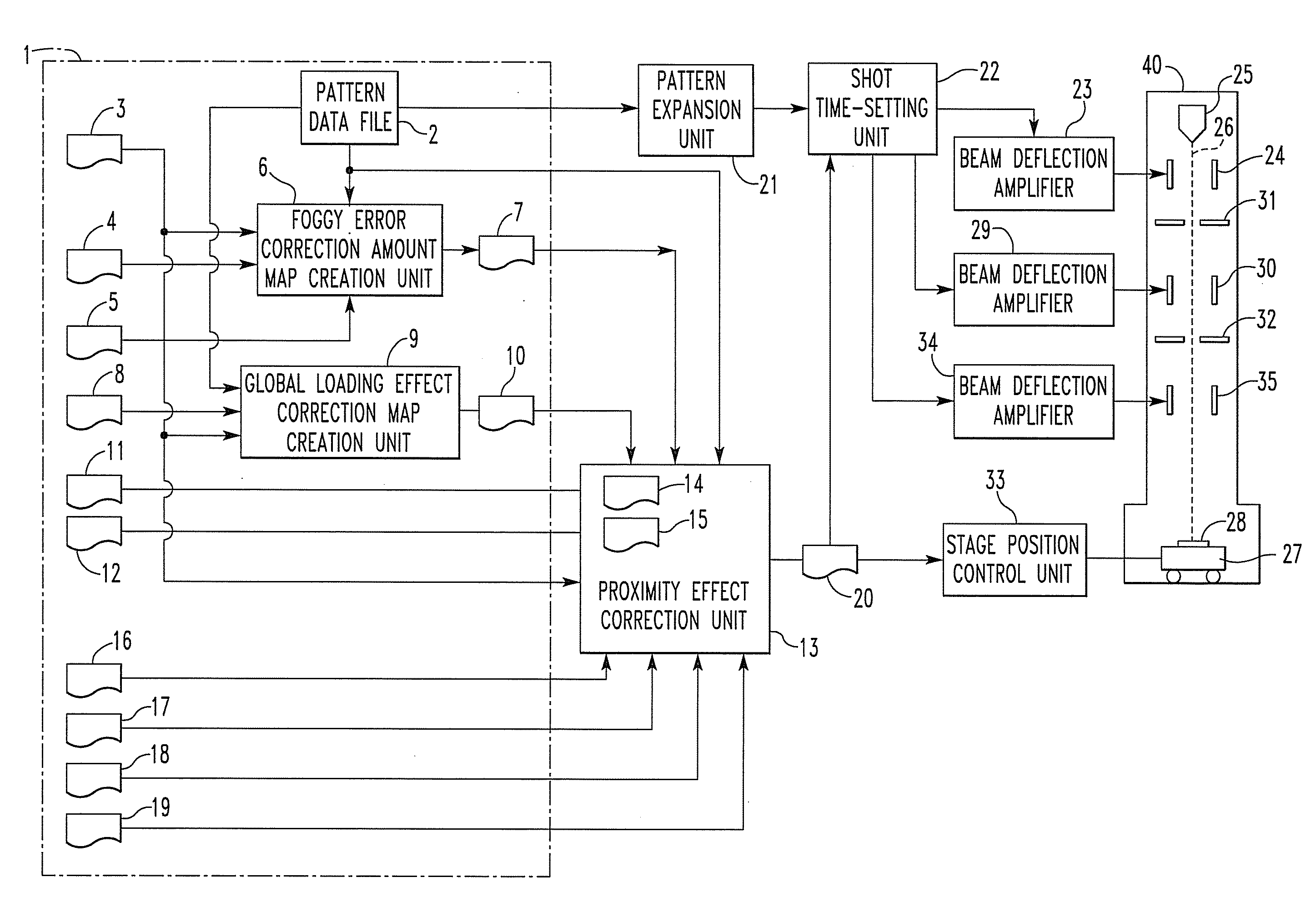
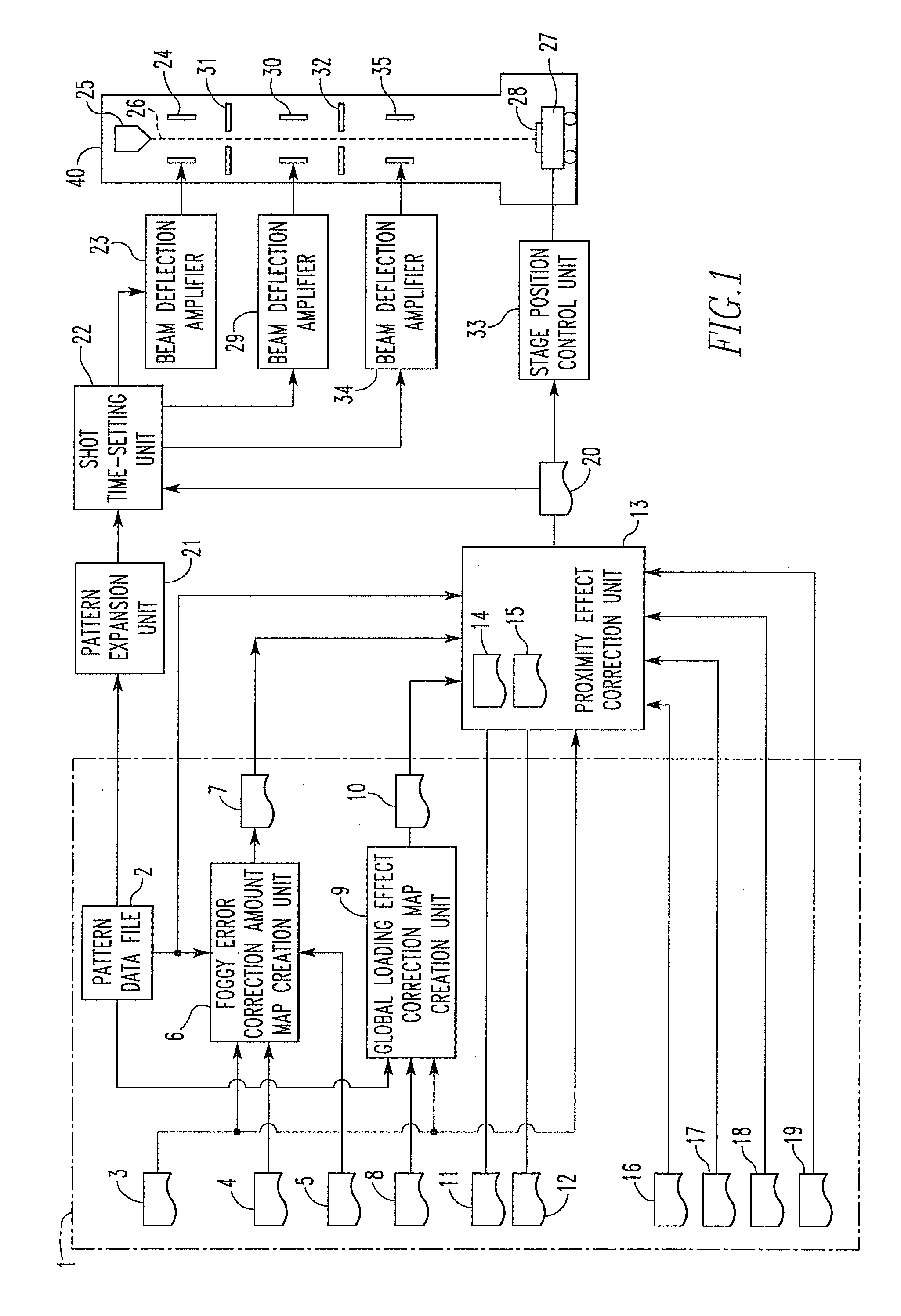
[0027]Embodiments of the present invention are hereinafter described in detail with reference to the drawings.

[0028]In the present invention, in order to form a pattern having desired dimensions on a material, the dose of a charged-particle beam on a resist applied on the surface of the material is varied. According to the present invention, dimensions can be controlled more accurately than the method of varying a design pattern itself. Various kinds of errors that are corrected by the present invention are first described.

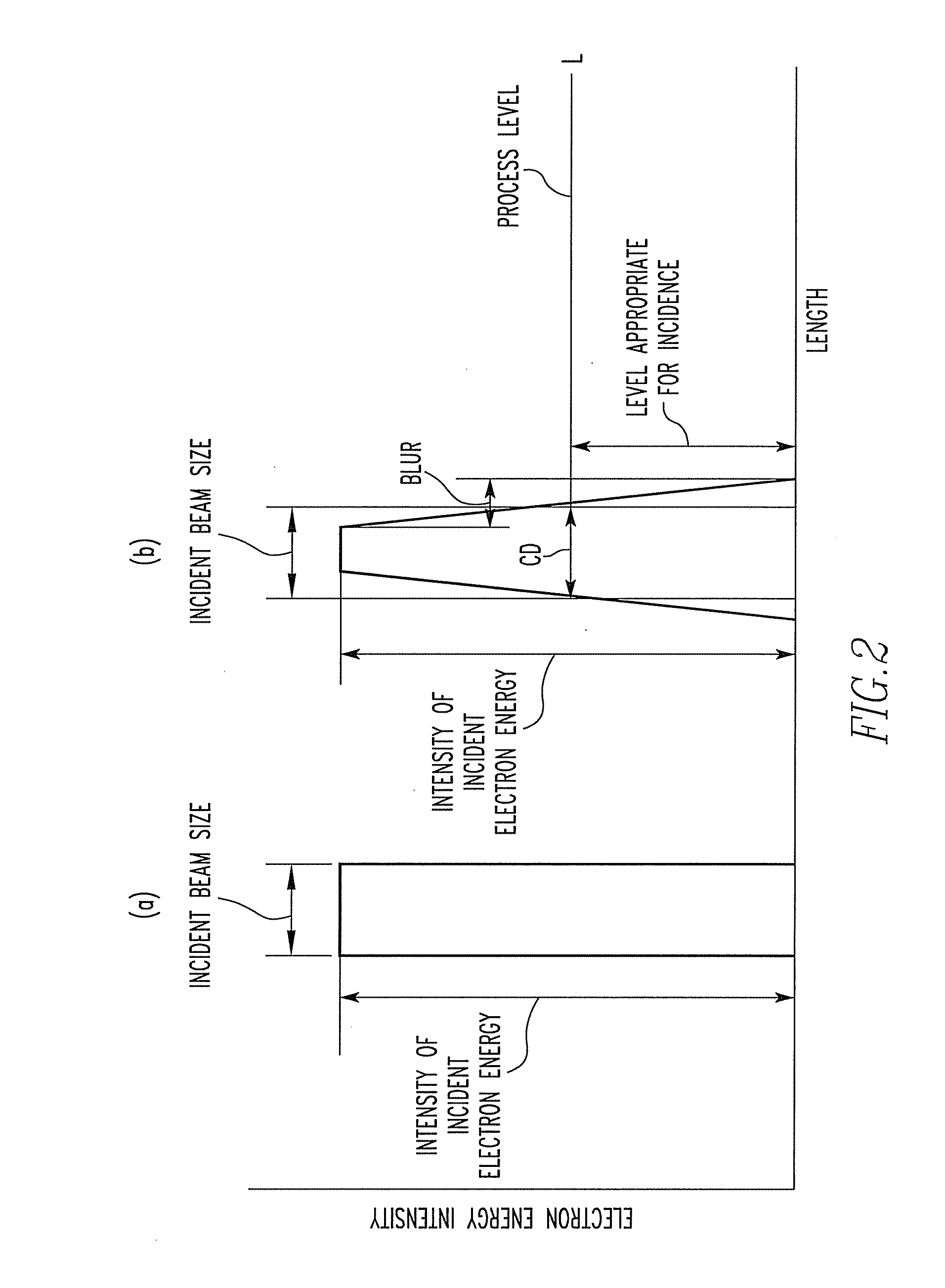
[0029](1) Proximity Effect Correction

[0030]In a method of charged-particle beam lithography, a charged-particle beam is scattered within a layer of resist (forward scattering) or transmitted through the layer of resist, enters the substrate, and is rescattered into the layer of resist from the substrate (backward scattering). Consequently, energy is stored in the unirradiated portions close to the irradiated portion. Therefore, if development is done, undeveloped ...


PUM


Abstract

Charged-particle beam lithography method and system. The lithography system has a map creation unit and a lithographic data creation unit. The map creation unit creates a proximity effect correction amount map from pattern data supplied from a pattern data file, pattern layout information, a foggy error correction amount map, loading effect correction amount maps, a process error correction amount map, a transfer error correction amount map, proximity effect correction parameters, and a proximity effect correction map. The lithographic data creation unit creates lithographic data based on the pattern data from the pattern data file, creates shot time data based on the proximity effect correction amount map from the map creation unit, and attaches the created shot time data to the lithographic data.

Description

BACKGROUND OF THE INVENTION[0001]1. Field of the Invention[0002]The present invention relates to a method and system for charged-particle beam lithography. It relates to finding an optimum lithography dose by performing correction computations taking account of mutual effects of proximity effect correction, foggy error correction, and process error correction and calculating the optimum dose based on the results of the computations.[0003]2. Description of Related Art[0004]A method of charged-particle beam lithography is a method for writing a desired pattern at a desired position on a material by applying a resist on a substrate to prepare the material and shooting a charged-particle beam at the desired position. It is thus possible to fabricate semiconductor devices of quite high density.[0005]In this method of charged-particle beam lithography, the dose is corrected for each shot in order to correct various effects including proximity effects, foggy errors, process errors, and tra...

Claims


Application Information

Patent Timeline
IPC IPC(8): G21K5/10
CPCB82Y10/00H01J37/3174B82Y40/00
Inventor KAWASE, YUICHI
Owner JEOL LTD
Why Eureka
Try Eureka