
Control valve for variable capacity compressors

a compressor and variable capacity technology, applied in the direction of valve operating means/release devices, machines/engines, positive displacement liquid engines, etc., can solve the problems of increasing the size and the inability to suitably control the degree of valve opening, and the increase of power consumption, so as to increase the full open flow rate, increase the size and weight, and save the weight of the control valve.

Inactive Publication Date: 2009-02-05
FUJIKOKI CORP
View PDF9 Cites 2 Cited by
  • Summary
  • Abstract
  • Description
  • Claims
  • Application Information

AI Technical Summary

Benefits of technology

[0021]The present invention has been made in view of the circumstances mentioned above and, therefore, an object of the present invention is to provide a control valve for a variable capacity compressor, which makes it possible to increase the full open flow rate so as to make it applicable to even a compressor of large capacity without inviting any substantial increase in size and weight, and to reduce the quantity of leakage of cooling medium from the valve chamber into the suction pressure cooling medium-introducing chamber to thereby make it possible to enhance the accuracy of control and to suppress the occurrence of operational failure including the clogging due to foreign substances, the locking of valve rod, etc.
[0029]In the control valve for a variable capacity compressor according to the present invention, since the control valve is provided with, for example, a couple of valve seats and also with a couple of valve body portions for concurrently opening or closing their respective valve seats, it is possible to increase the full open flow rate without enlarging the aperture of valve seat, thereby making the control valve applicable to even a compressor of large capacity without inviting any substantial increase in size and weight.
[0030]Furthermore, differently from the conventional control valves, since the outer diameter of the shank portion of valve rod to be slidably moved in the guide hole is not required to be almost the same as that of the aperture of valve seat, it is possible to considerably decrease, as compared with the conventional valve rod, the outer diameter of the sliding portion of valve rod that slidably contacts with the guide hole, even when the full open flow rate were increased. Therefore, it is possible to miniaturize the control valve and to save the weight of control valve and, at the same time, since the contacting area between the guide hole and the valve rod 15 can be decreased, the sliding frictional resistances of these contacting portions can be minimized.
[0031]Additionally, since a total cross-sectional area of the gap to be formed between the slide-contacting surface of the shank portion of valve rod and that of the guide hole can be decreased, it is possible to suppress the occurrence of operational failure such as the clogging due to foreign substances, the locking of valve rod, etc.
[0032]In the case of the conventional control valve of this kind, the cooling medium having a discharge pressure “Pd” that has been introduced into the valve chamber from the cooling medium inlet port is permitted to leak toward the suction pressure cooling medium-introducing chamber after passing through a gap formed between the slide-contacting surface of the shank portion of valve rod and that of the guide hole. Whereas, in the case of the control valve of the present invention, the cooling medium that can be leaked toward the suction pressure cooling medium-introducing chamber is restricted to one which is throttled by both the upper valve seat and the upper valve body portion so as to have a lower outlet pressure Pc as compared with the discharge pressure “Pd”. Therefore, the quantity of leakage can be decreased, resulting in the enhancement of control accuracy of the control valve and in the suppression of occurrence of operational failure such as the clogging due to foreign substances, the locking of valve rod, etc.

Problems solved by technology

If such a situation is caused to generate, it is no longer possible to suitably control the degree of valve opening.
As described above, since the guide hole 19b and the intermediate large diameter shank portion 15b are both required to be increased in diameter, the above-described structure leads to the increase in size and weight of the control valve and, at the same time, since the contacting area between the guide hole 19b and the intermediate large diameter shank portion 15b is also caused to increase, the sliding frictional resistance at this contacting area is caused to increase, so that the electromagnetic actuator 30 is required to be selected from those having a larger output, resulting in increase of power consumption.
Further, since the total cross-sectional area of the gap is caused to increase, other problems may be caused to arise such as operational failure including the clogging due to foreign substances, the locking of valve rod, etc.

Method used


Image

  • Control valve for variable capacity compressors
  • Control valve for variable capacity compressors
  • Control valve for variable capacity compressors

Examples


Embodiment Construction

[0039]Next, a specific embodiment of the control valve for a variable capacity compressor according to the present invention will be explained in detail with reference to the drawings.

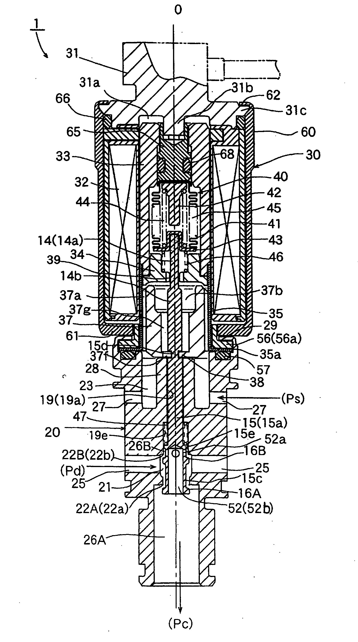
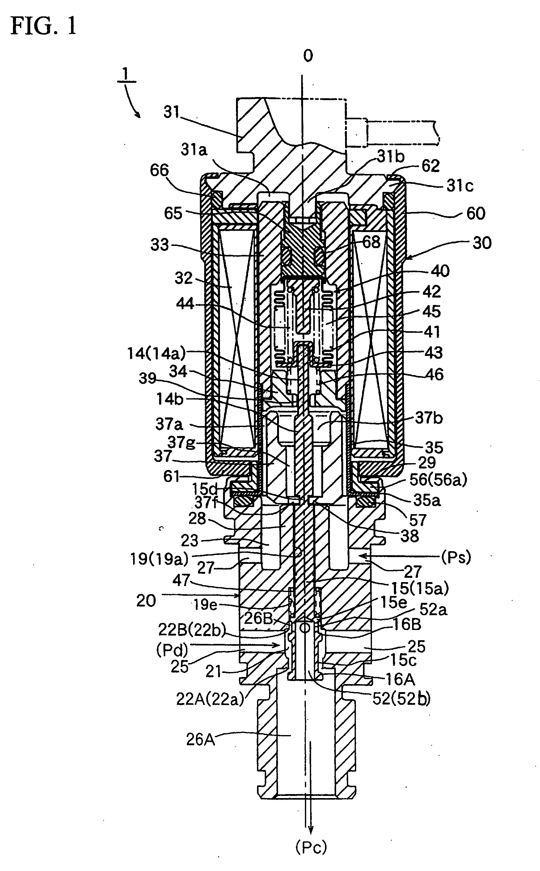
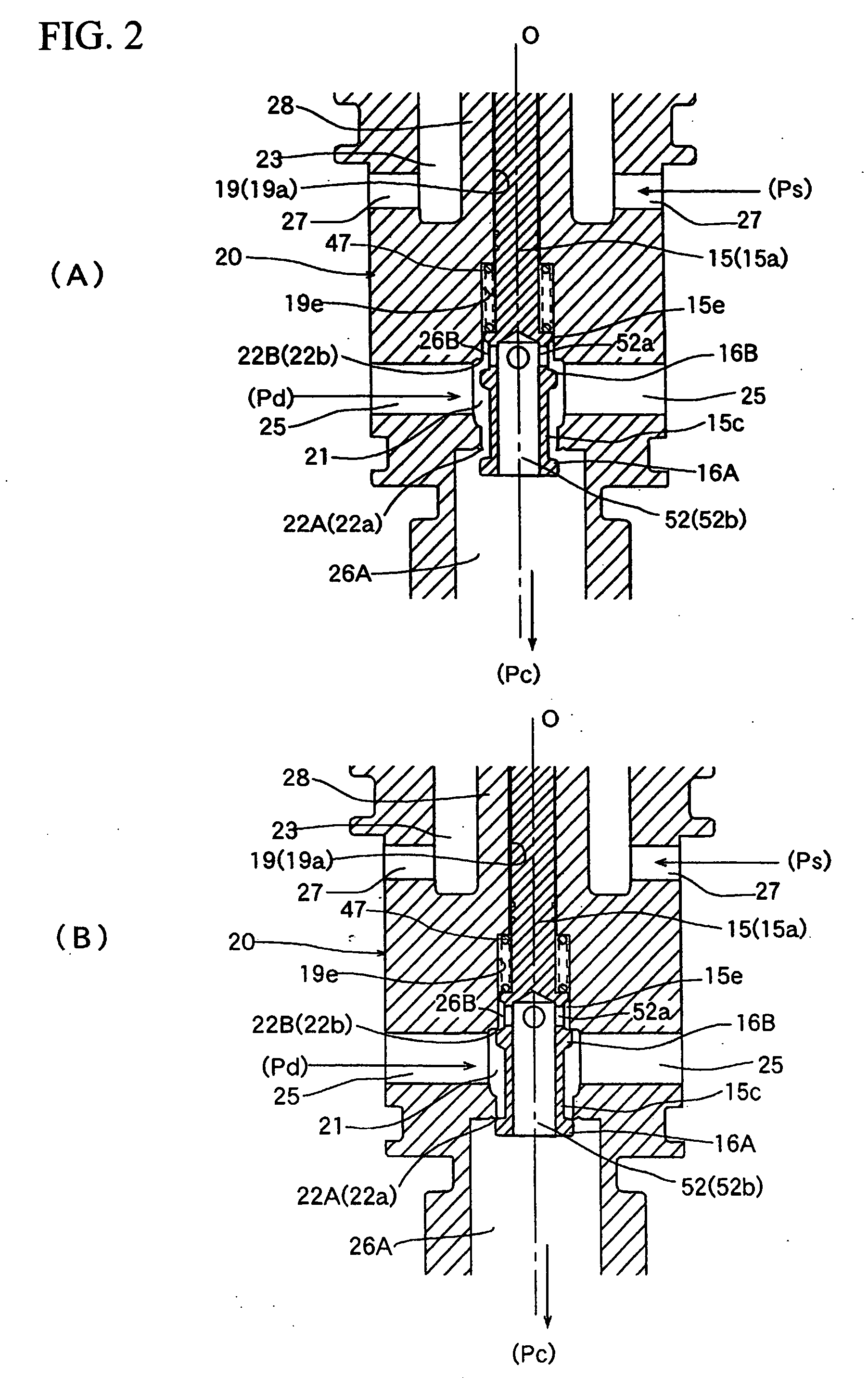
[0040]FIG. 1 is a longitudinal sectional view illustrating one embodiment of the control valve for a variable capacity compressor according to the present invention; FIG. 2(A) is an enlarged longitudinal sectional view illustrating a main portion of the control valve shown in FIG. 1 wherein the control valve is opened; and FIG. 2(B) is an enlarged longitudinal sectional view illustrating a main portion of the control valve shown in FIG. 1 wherein the control valve is closed. In the control valve 1 for a variable capacity compressor shown in FIGS. 1, 2(A) and 2(B), the parts or components which correspond to those of the conventional control valve 5 for a variable capacity compressor which is shown in FIGS. 3, 4(A) and 4(B) will be identified by the same reference numbers to thereby omit the repeated ex...


PUM


Abstract

A control valve for a variable capacity compressor, which makes it possible to increase the full open flow rate so as to make it applicable to even a compressor of large capacity without inviting any substantial increase in size and weight, and to minimize the quantity of leakage of cooling medium from the valve chamber into the suction pressure cooling medium-introducing chamber to thereby make it possible to enhance the accuracy of control and to suppress the occurrence of operational failure including the clogging due to foreign substances, the locking of valve rod, etc. The valve rod is provided, at a lower portion thereof, with a lower valve body portion (16A) and an upper valve body portion (16B), and the valve chamber is provided with a lower valve seat (22a) and an upper valve seat (22b) in such a manner that the lower valve body portion (16A) and the upper valve body portion (16B) are concurrently enabled to detachably contact with their respective valve seats, and a lower cooling medium outlet chamber (26A) and an upper cooling medium outlet chamber (26B) are disposed on the downstream sides of the lower valve seat (22a) and of the upper valve seat (22b), respectively.

Description

BACKGROUND OF THE INVENTION[0001]1. Field of the Invention[0002]The present invention relates to a control valve for variable capacity compressors which is designed to be employed in air conditioners for vehicles, etc., and in particular to a control valve for variable capacity compressors which is designed such that a valve rod which is slidably and snugly inserted into a guide hole can be scarcely brought into malfunctioning.[0003]2. Description of the Related Art[0004]The control valve for variable capacity compressors which is designed to be employed in air conditioners for vehicles, etc. is generally constructed such that a cooling medium having a discharge pressure “Pd” is permitted to enter into the crank chamber of compressor from the discharge chamber of compressor so as to adjust the pressure “Pc” inside the crank chamber. In this case, the flow rate of cooling medium having a discharge pressure “Pd” to the crank chamber is restricted in such a manner that the quantity of ...

Claims


Application Information

Patent Timeline
Patent Type & Authority Applications(United States)
IPC IPC(8): F16K31/06
CPCF04B27/1804F04B2027/1859F04B2027/1854F04B2027/1827F04B27/14F04B39/10
Inventor MORISAWA, DAISUKEKUME, YOSHIYUKI
Owner FUJIKOKI CORP
Learn More