Electron emission source, electron emission device and method of preparing the electron emission source

Inactive Publication Date: 2009-02-05
SAMSUNG SDI CO LTD
View PDF2 Cites 8 Cited by
  • Summary
  • Abstract
  • Description
  • Claims
  • Application Information

AI Technical Summary

Benefits of technology

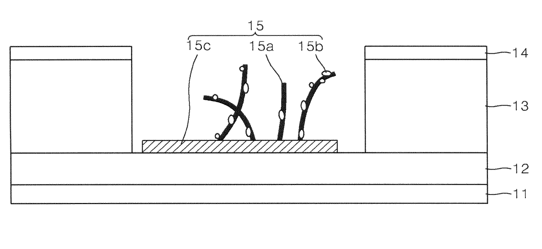
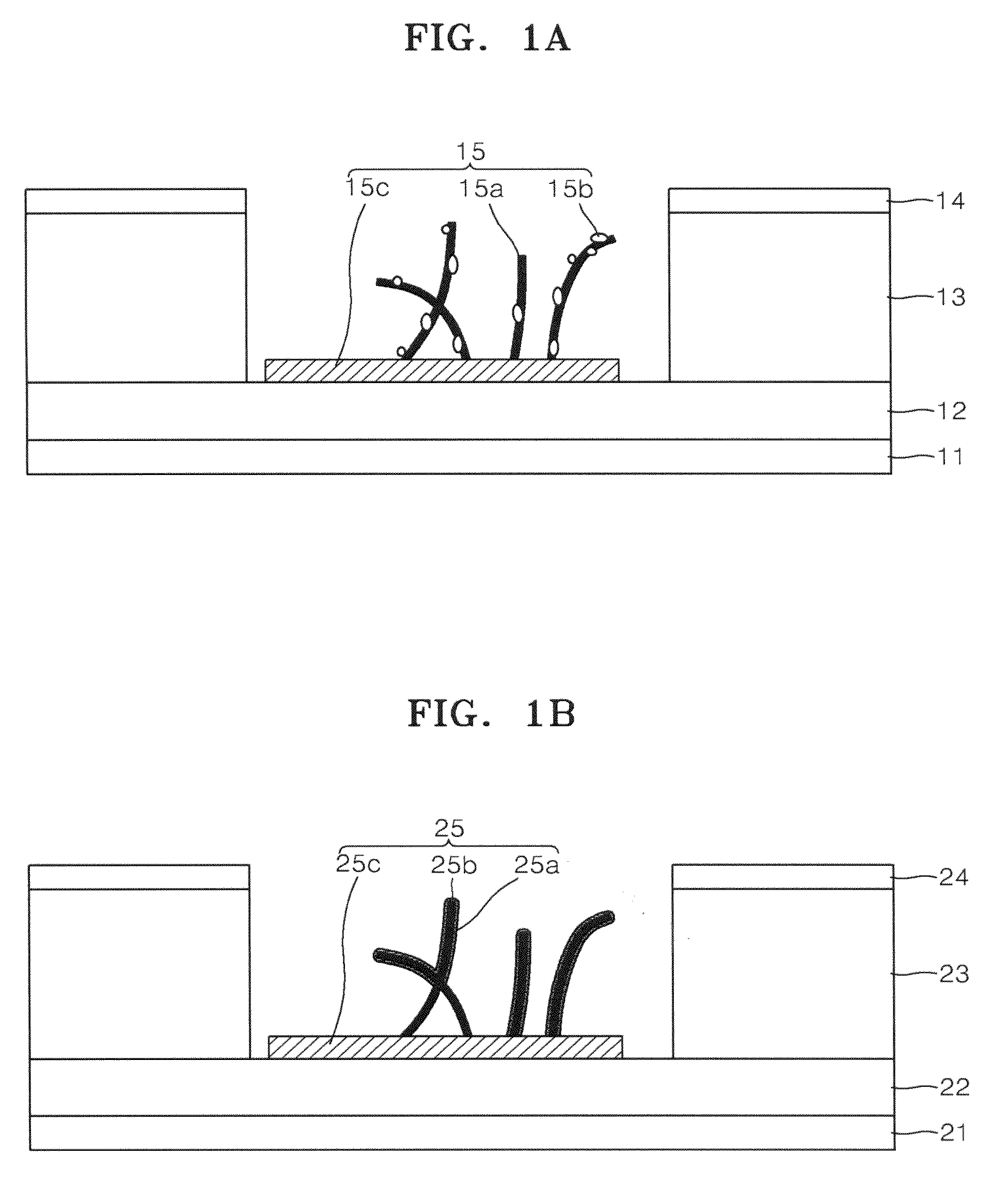
[0013]The electron emission sources according to embodiments of the present invention have excellent field emission efficiencies and long lifetimes. Thus, electron emissio

Problems solved by technology

However, in conventional electron emission sources, during operation of the electron emission device, active gases are absorbed into the electron emission material (e.g. CNTs or the like), or the electron and atom stru

Method used


Image

  • Electron emission source, electron emission device and method of preparing the electron emission source
  • Electron emission source, electron emission device and method of preparing the electron emission source
  • Electron emission source, electron emission device and method of preparing the electron emission source

Examples


Example

Example 1

[0088](A) Preparation of Carbon Nanotubes Coated with Pd

[0089]0.5 g of carbon nanotube (manufactured by CNI) was added to 100 ml of deionized water, and then sonicated for 5 minutes. First, 10 wt % of a PdCl2 solution was separately prepared by adding palladium chloride (PdCl2) powder (manufactured by Aldrich) to deionized water, and then 20 ml of the PdCl2 solution was added to the carbon nanotube-containing deionized water while being sonicated. 20 ml of 1 M NaBH4 solution was dropped into the mixture using a micropipette, and then allowed to stand for 10 minutes. The resultant was filtered using a 7 μm filter, and then washed using deionized water. Then, the resultant was dried for 2 hours in an oven at a temperature of 100° C. (at atmospheric atmosphere) to obtain carbon nanotubes coated with Pd.

[0090]FIG. 5A is a transmission electron microscope (TEM) image of the carbon nanotubes coated with Pd. FIG. 5B is an electronic data change (EDX) graph of the carbon nanotubes ...

Example

Example 2

[0093](A) Preparation of Carbon Nanotubes Coated with SnO2

[0094]0.5 g of carbon nanotubes (manufactured by CNI) was added to 100 ml of deionized water, and then sonicated for 5 minutes. First, 10 wt % of a SnCl2 solution was separately prepared by adding tin chloride (SnCl2) powder (manufactured by Aldrich) to deionized water, and then 20 ml of the SnCl2 solution was added to the carbon nanotube-containing deionized water while being sonicated. Then, the mixture was put into an electric furnace under atmospheric pressure, and then the temperature of the electric furnace was raised to 400° C. The temperature of the electric furnace remained at 400° C. for 20 minutes, and was then cooled down to room temperature. The resultant was filtered using a 7 μm filter, and then washed using deionized water. Then, the resultant was dried for 2 hours in an oven at a temperature of 100° C. (atmospheric pressure) to obtain carbon nanotubes coated with SnO2.

[0095]FIG. 6 is a transmission ...

Example

Example 3

[0098](A) Preparation of Carbon Nanotube Coated with Ti

[0099]A carbon nanotube coated with Ti was prepared as in Example 1, except that titanium chloride (TiCl3) powder (manufactured by Aldrich) was used instead of PdCl2 powder.

[0100](B) Preparation of Electron Emission Source including the Carbon Nanotube Coated with Ti

[0101]An electron emission source was prepared as in Example 1, except that the carbon nanotubes coated with Ti were used instead of the carbon nanotubes coated with Pd. This electron emission source is referred to as Sample 3.

Comparative Example

[0102]An electron emission source was prepared as in Example 1, except that carbon nanotubes (manufactured by CNI) were used instead of the carbon nanotubes coated with Pd. This electron emission source is referred to as Comparative Sample A.

Evaluation Example

[0103]FIGS. 7 and 8 compare the field emission efficiency and lifetime evaluation results of Sample 3 and Comparative Sample A. Field emission efficiency was ev...


PUM


Abstract

Electron emission sources, electron emission devices including the electron emission sources, and methods of making the electron emission sources are provided. The electron emission source includes a carbon-based material, and a degradation prevention material for preventing degradation of the carbon-based material. A binding energy between the degradation prevention material and external oxygen is greater than a binding energy between the carbon-based material and the external oxygen. The electron emission sources have excellent field emission efficiencies and long lifetimes.

Description

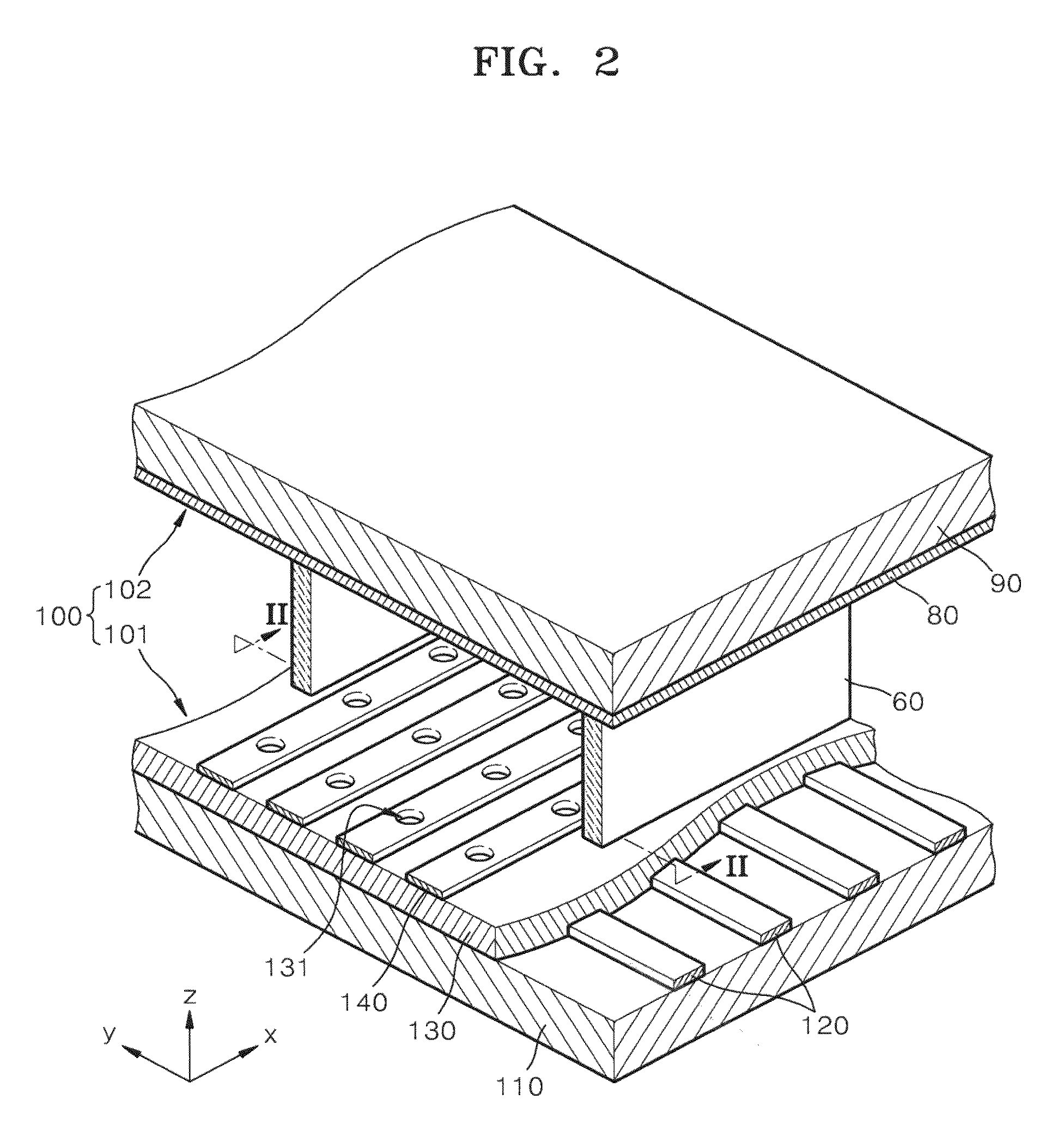
CROSS-REFERENCE TO RELATED PATENT APPLICATION[0001]This application claims priority to and the benefit of Korean Patent Application No. 10-2007-0076429, filed on Jul. 30, 2007 in the Korean Intellectual Property Office, the entire content of which is incorporated herein by reference.BACKGROUND OF THE INVENTION[0002]1. Field of the Invention[0003]The present invention relates to electron emission sources, electron emission devices, and methods of preparing the electron emission sources. More particularly, the invention is directed to an electron emission source comprising a carbon-based material and a degradation prevention material for preventing degradation of the carbon-based material, an electron emission device including the electron emission source, and a method of preparing the electron emission source.[0004]2. Description of the Related Art[0005]An electron emission device is a device that emits light by emitting electrons from an electron emission source under an electric fi...

Claims


Application Information

Patent Timeline
IPC IPC(8): H01J1/02
CPCH01J1/304H01J2201/30453H01J2201/30426H01J3/021B82Y40/00H01J9/025
Inventor CHO, YOUNG-MIKIM, CHANG-WOOKMOON, HEE-SUNG
Owner SAMSUNG SDI CO LTD
Why Eureka
Try Eureka