
Method and device for determining a gradient-limited cumulative setpoint torque from a setpoint torque of a closed-loop speed control

a technology of closed-loop speed control and cumulative setpoint torque, which is applied in the direction of motor/generator/converter stopper, electric control, dynamo-electric converter control, etc., can solve the problems of delay in torque generation and reduction, annoy the driver, and affect the driving comfort. , to achieve the effect of high control quality and high dynamic performan

Inactive Publication Date: 2009-02-05
ROBERT BOSCH GMBH
View PDF4 Cites 45 Cited by
  • Summary
  • Abstract
  • Description
  • Claims
  • Application Information

AI Technical Summary

Benefits of technology

[0011]It is an object of the present invention to provide a method and a device for torque formation in a drive motor, in which comfortable load changes are achievable with high dynamic performance while considering an intervention by the closed-loop speed control in an operation having rpm-regulated control close the to idling speed, with high control quality of the closed-loop speed control.
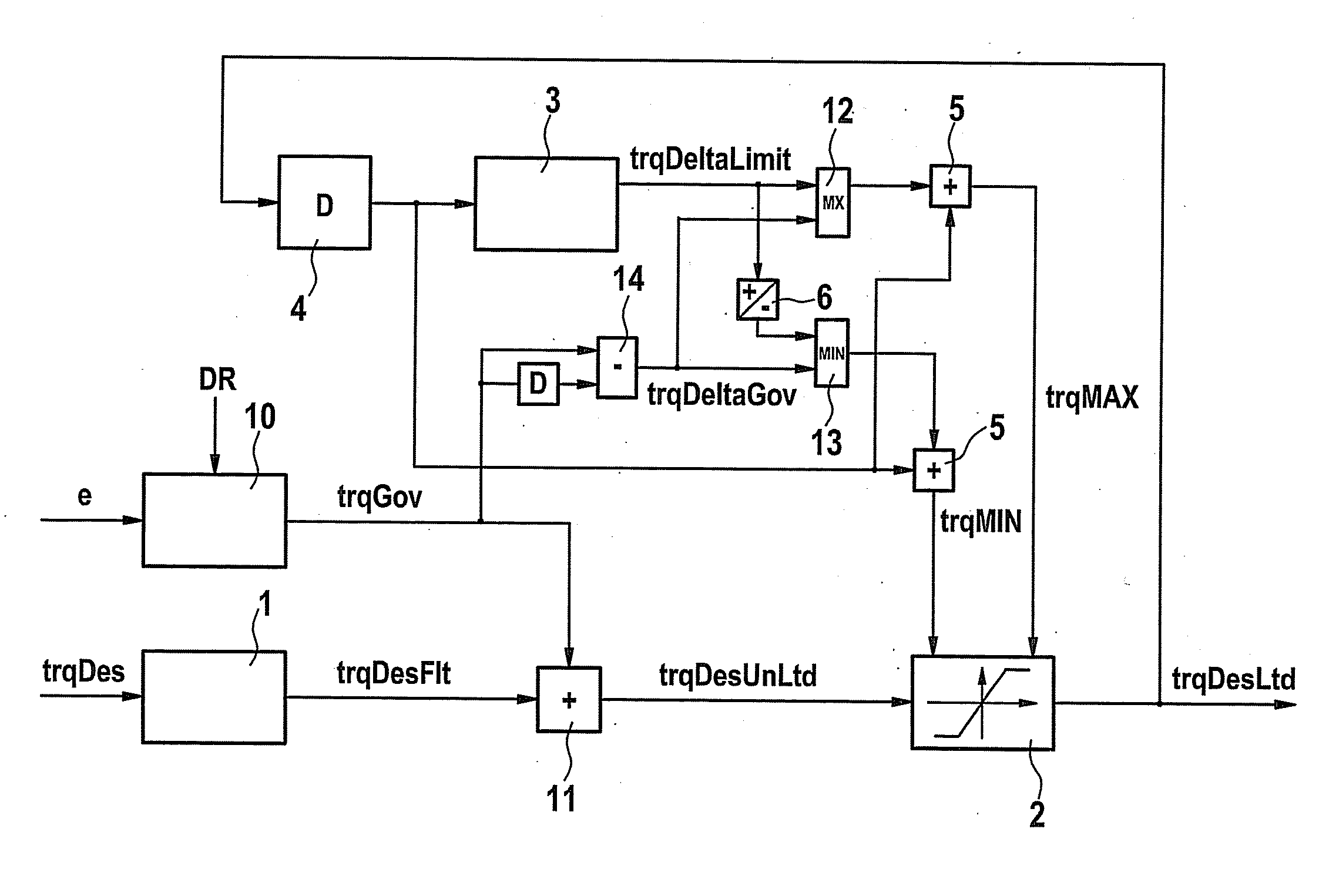
[0013]The core of the present invention is to determine a combined, unlimited cumulative setpoint torque from the controller setpoint torque of a closed-loop speed control, and from a setpoint drive torque of additional requesters (driver, driver-assistance systems, etc.), and to implement a rate-of-change limitation of this unlimited cumulative setpoint torque. In so doing, the controller setpoint torque of the closed-loop speed control and / or its gradient influences at least one limit of the rate-of-change limitation, i.e., the upper and / or the lower limit, for the unlimited cumulative setpoint torque. This achieves high driving comfort while providing high control quality at the same time.

Problems solved by technology

Rapid load changes or gear-change operations in motor vehicles can cause jerking, which is annoying to the driver and has a detrimental effect on the driving comfort.
This causes a delay in the torque generation and reduction.
The interaction becomes problematic with an additional speed controller or idle controller which specifies a controller setpoint torque that is to prevent such things as, for example, chocking of a combustion engine used as drive motor.
However, an influencing of the controller setpoint torque by the following reference formation is not practicable from the viewpoint of the closed-loop speed control.
For one, the low-pass filtering delays controller setpoint torque, which causes a delay in a compensation torque induced by the closed-loop speed control, so that, for instance, choking of the combustion engine becomes more likely.
For another, the behavior of the controlled system varies considerably due to the non-linearity in the rate-of-change limitation, which requires a very robust controller and thus has a considerable adverse effect on the quality of the closed loop control.
Furthermore, there are problems in the transitions between rpm-regulated operation close to idling speed and torque-controlled operation above idling speed due to the fact that the gradient of the controller setpoint torque has an additional effect on the gradient of the cumulative setpoint torque.
This partially compensates for the rise in the limited setpoint torque, or it may even cause undershooting in the cumulative setpoint torque.
The acceleration no longer progresses optimally, and the achievable dynamic performance is limited.
The undershooter may cause the cumulative setpoint torque to cross zero multiple times, combined with poor behavior of the drive in a load change.

Method used


Image

  • Method and device for determining a gradient-limited cumulative setpoint torque from a setpoint torque of a closed-loop speed control
  • Method and device for determining a gradient-limited cumulative setpoint torque from a setpoint torque of a closed-loop speed control
  • Method and device for determining a gradient-limited cumulative setpoint torque from a setpoint torque of a closed-loop speed control

Examples


Embodiment Construction

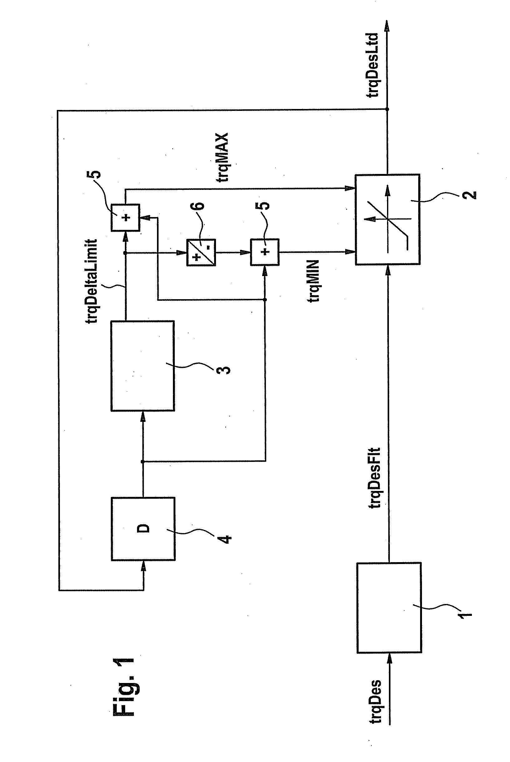
[0027]One possible realization of torque formation is shown in FIG. 1. A setpoint drive torque trqDes requested by, for instance, a driver (via the gas pedal position) or requested by other vehicle devices is forwarded to a filter stage 1 where it is low-pass-filtered. Filtered setpoint drive torque trqDesFlt obtained in this manner is then forwarded to a rate-of-change limiter 2, which implements a rate-of-change limitation (limitation of the first derivative) of filtered setpoint drive torque trqDesFlt. A limited setpoint torque trqDesLtd is obtained as output of rate-of-change limiter 2.

[0028]Rate-of-change limiter 2 implements the rate-of-change limitation by being supplied with a highest permitted value trqMAX and a lowest permitted value trqMIN for limited setpoint torque trqDesLtd. If filtered setpoint drive torque trqDesFlt transmitted to rate-of-change limiter 2 exceeds the highest permitted value trqMAX for limited setpoint torque trqDesLtd, or if it undershoots lowest per...


PUM


Abstract

In a method for determining a gradient-limited setpoint torque from a requested setpoint drive torque and a controller setpoint torque of a closed-loop speed control, the gradient of an unlimited cumulative setpoint torque, which is a function of the requested setpoint drive torque and the controller setpoint torque of the closed-loop speed control, is limited in a region of the zero crossing of the gradient-limited setpoint torque by a rate-of-change limitation to a maximally permitted or a minimally permitted value. The maximally permitted or the minimally permitted value of the rate-of-change limitation is a function of the controller setpoint torque of the closed-loop speed control.

Description

BACKGROUND OF THE INVENTION[0001]1. Field of the Invention[0002]The present invention relates to a method and a device for forming a setpoint torque of a drive motor, in particular in connection with an operating mode of the drive motor having closed-loop speed control.[0003]2. Description of Related Art[0004]Rapid load changes or gear-change operations in motor vehicles can cause jerking, which is annoying to the driver and has a detrimental effect on the driving comfort. Known methods for reducing judder vibrations are based on avoiding an excitation of the drive train due to rapid load changes. In rapid variations, the setpoint drive torque requested by the driver via the drive pedal (or by driver-assistance systems) is therefore low-pass filtered with the aid of reference-forming elements, and / or its rate of change is restricted. This causes a delay in the torque generation and reduction.[0005]In addition, measures are taken in zero crossings of the drive torque, i.e., in the tr...

Claims


Application Information

Patent Timeline
Patent Type & Authority Applications(United States)
IPC IPC(8): H02P7/00
CPCF02D11/105F02D41/0205F02D41/107F02D2250/28F02D2250/18F02D2250/21F02D2250/26F02D41/1497
Inventor FALKENSTEIN, JENS-WERNER
Owner ROBERT BOSCH GMBH
Learn More