Voltage adjusting apparatus

a voltage adjusting and apparatus technology, applied in the direction of battery/fuel cell control arrangement, safety/protection circuit, electric devices, etc., can solve the problems of increasing the cost of the electric control apparatus with self-diagnosis, the high-voltage battery for the motor traveling may have a malfunction, etc., to achieve more reliable, reduce cost, and perform safely

Active Publication Date: 2009-02-05
YAZAKI CORP
View PDF2 Cites 18 Cited by
  • Summary
  • Abstract
  • Description
  • Claims
  • Application Information

AI Technical Summary

Benefits of technology

[0019]According to the present invention, the low-voltage system and the high-voltage system monitor about malfunctions to each other, and the voltage adjusting apparatus more reliable can be realized by shifting to a safe action when the malfunction is occurred at the low-voltage system or the high-voltage system. The cost can be reduced by using no duplex fail-safe.
[0020]According to the present invention, the self-diagnostics about the malfunction can be performed by the malfunction judging period counted by t

Problems solved by technology

According to the above equalizing apparatus, when the control unit stops functionally during adjusting (equalizing), the equalizing action continues to consume energy of unit cells of the high-voltage battery, so that the high-volta

Method used


Image

  • Voltage adjusting apparatus
  • Voltage adjusting apparatus
  • Voltage adjusting apparatus

Examples


first embodiment

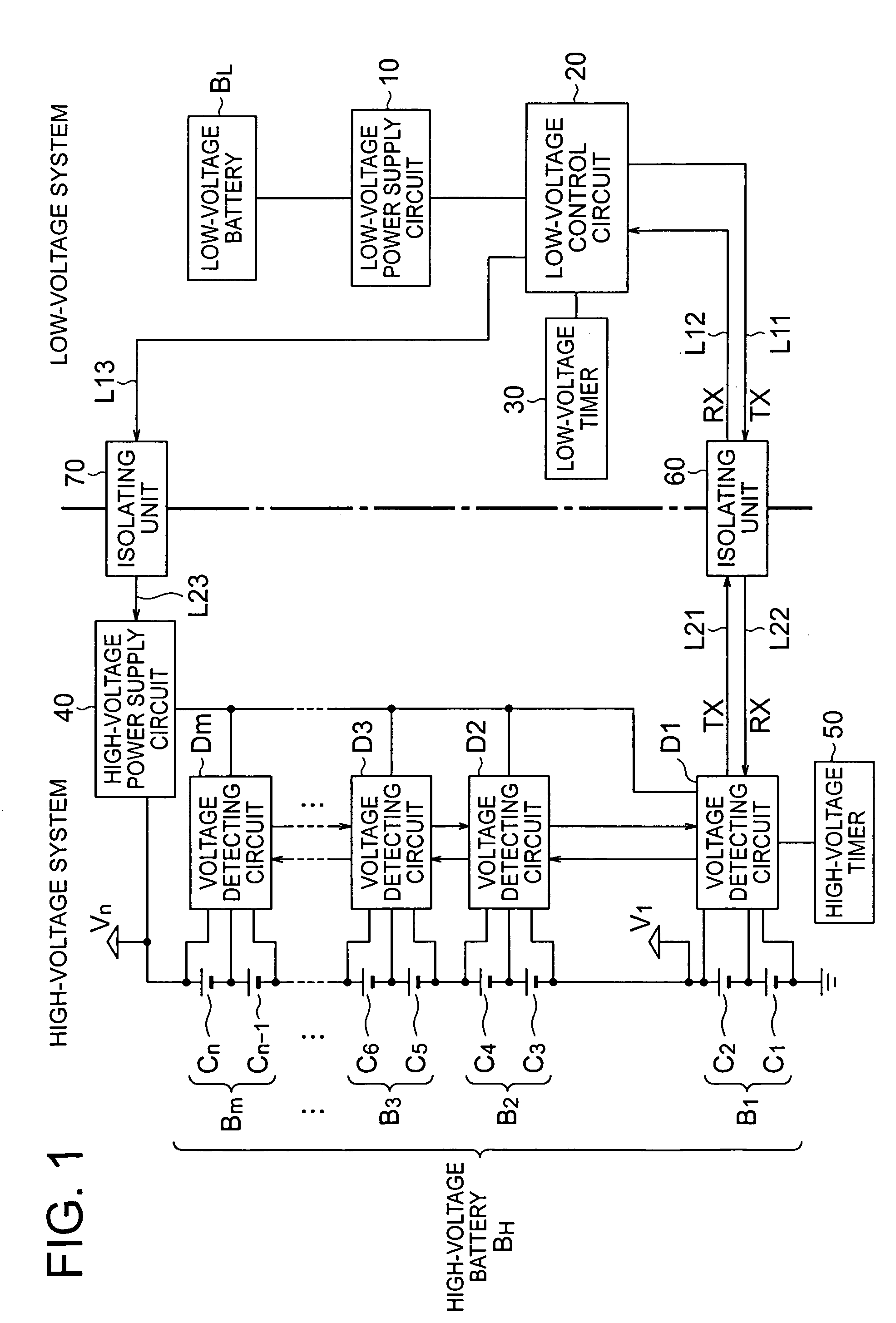
[0031]FIG. 1 is a block diagram showing a first embodiment of a voltage adjusting apparatus according to the present invention. In FIG. 1, a low-voltage battery (on-vehicle low-voltage battery) BL is formed by one secondary battery. The low-voltage battery BL is used as a power supply for an auxiliary unit, such as a starter (not shown) starting an engine, and connected at both terminals of the battery BL to an alternator (not shown) as a charger according to a requirement.

[0032]A high-voltage battery (on-vehicle high-voltage battery) BH is formed as a battery pack, and used as a drive power supply for a drive motor (not shown) of a hybrid engine vehicle (HEV) using in parallel an engine (not shown) and the drive motor for traveling. Both terminals of the battery BH are connected to an alternator (not shown) as a charger according to a requirement.

[0033]The high-voltage battery BH is formed with “m” (m: any integer) blocks B1-Bm. Each block B1-Bm includes a plurality of unit cells (...

second embodiment

[0054]The second embodiment of a voltage adjusting apparatus according to the present invention is described hereafter. In the first embodiment, the equalizing circuits E1, E2 in the voltage detecting circuits D1-Dm are connected respectively to the unit cell of each block. In the second embodiment, one equalizing circuit is provided to each block and connected to one unit cell selected from a plurality of unit cells in each block.

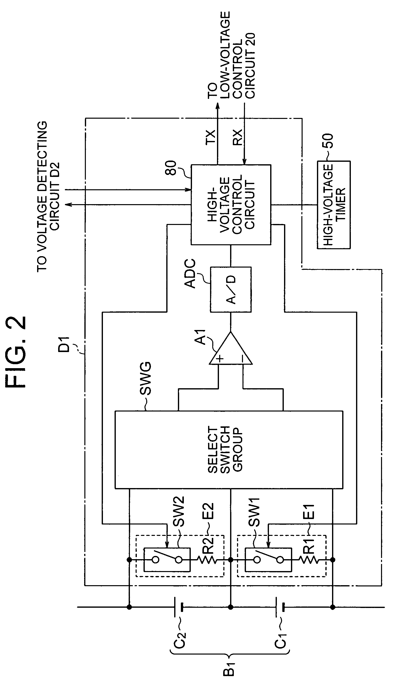
[0055]FIG. 5 is a circuit diagram showing an example of a structure of a voltage detecting circuit of the second embodiment of the voltage adjusting apparatus according to the present invention. The voltage detecting circuit D1 includes a select switch group SWG selecting one unit cell from among unit cells C1, C2 forming the block B1, a differential amplifier A1 detecting a voltage value between both electrodes of the one unit cell selected by the select switch group SWG, an A / D converter ADC digitally converting the voltage value detected by the differen...


PUM


Abstract

For providing a reliable voltage adjusting apparatus in low cost, a low-voltage control apparatus controls a high-voltage power supply circuit to be switched power off by transmitting a power-off signal through a second communication line arranged between the high-voltage power supply circuit and itself through an isolation unit when an information signal from an equalizing apparatus is not transmitted within a predetermined first malfunction judging period. The equalizing apparatus stops an equalizing process in itself when the information signal from the low-voltage control unit

Description

[0001]The priority application Number Japan Patent Application 2007-198932 upon which this patent application is based is hereby incorporated by reference.BACKGROUND OF THE INVENTION[0002]1. Field of the Invention[0003]The present invention relates to a voltage adjusting apparatus, especially a voltage adjusting apparatus used for a hybrid vehicle (HEV) to detect a voltage value of an on-vehicle battery.[0004]2. Description of the Related Art[0005]At present time, a hybrid vehicle driven by usage in parallel of an engine and a motor for traveling has become popular. An electric circuit of the hybrid vehicle includes a low-voltage system for driving the engine and a high-voltage system for driving the motor for traveling. The low-voltage system has an on-vehicle low-voltage battery of 12 volts. The high-voltage system has an on-vehicle high-voltage battery formed by a battery pack in which a plurality of unit cells is connected in series. The high-voltage battery is given a high volt...

Claims


Application Information

Patent Timeline
IPC IPC(8): H02J7/36H02J7/02B60L3/00B60L3/04B60R16/03H02J7/00
CPCH02J7/0018Y02T10/7055H02J7/0026B60L3/0046B60L3/04B60L3/12B60L7/12B60L2240/547B60L2240/549B60L2240/80Y02T90/16Y02T10/70B60L50/16B60L58/14B60L58/22B60L58/20Y02T10/7072H02J7/00306
Inventor ISHIKAWA, SATOSHISEKIZAKI, MASASHIOKAMOTO, HAJIME
Owner YAZAKI CORP
Why Eureka
Try Eureka