Exposure apparatus, exposure method, and method for manufacturing display panel substrate

a technology of display panel substrate and exposure apparatus, which is applied in the direction of photomechanical treatment, printing, instruments, etc., can solve the problems of easy measurement error, reproducibility of measurement results, and increased cost of expensive masks, so as to achieve high precision and high precision , the effect of high quality substrates

Inactive Publication Date: 2009-02-05
HITACHI HIGH-TECH CORP
View PDF1 Cites 1 Cited by
  • Summary
  • Abstract
  • Description
  • Claims
  • Application Information

AI Technical Summary

Benefits of technology

[0020]The exposure apparatus or exposure method of the present invention is adopted to expose a substrate. Since the substrate can be positioned

Problems solved by technology

The cost of the expensive mask is further increased.
Thus, measurement errors may easily occur.
However,

Method used


Image

  • Exposure apparatus, exposure method, and method for manufacturing display panel substrate
  • Exposure apparatus, exposure method, and method for manufacturing display panel substrate
  • Exposure apparatus, exposure method, and method for manufacturing display panel substrate

Examples


Embodiment Construction

[0036]Reference will now be made in detail to the present preferred embodiments of the invention, examples of which are illustrated in the accompanying drawings. Wherever possible, the same reference numbers are used in the drawings and the description to refer to the same or like parts.

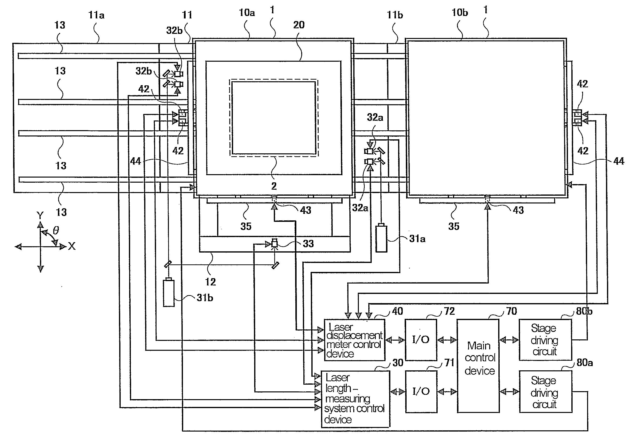
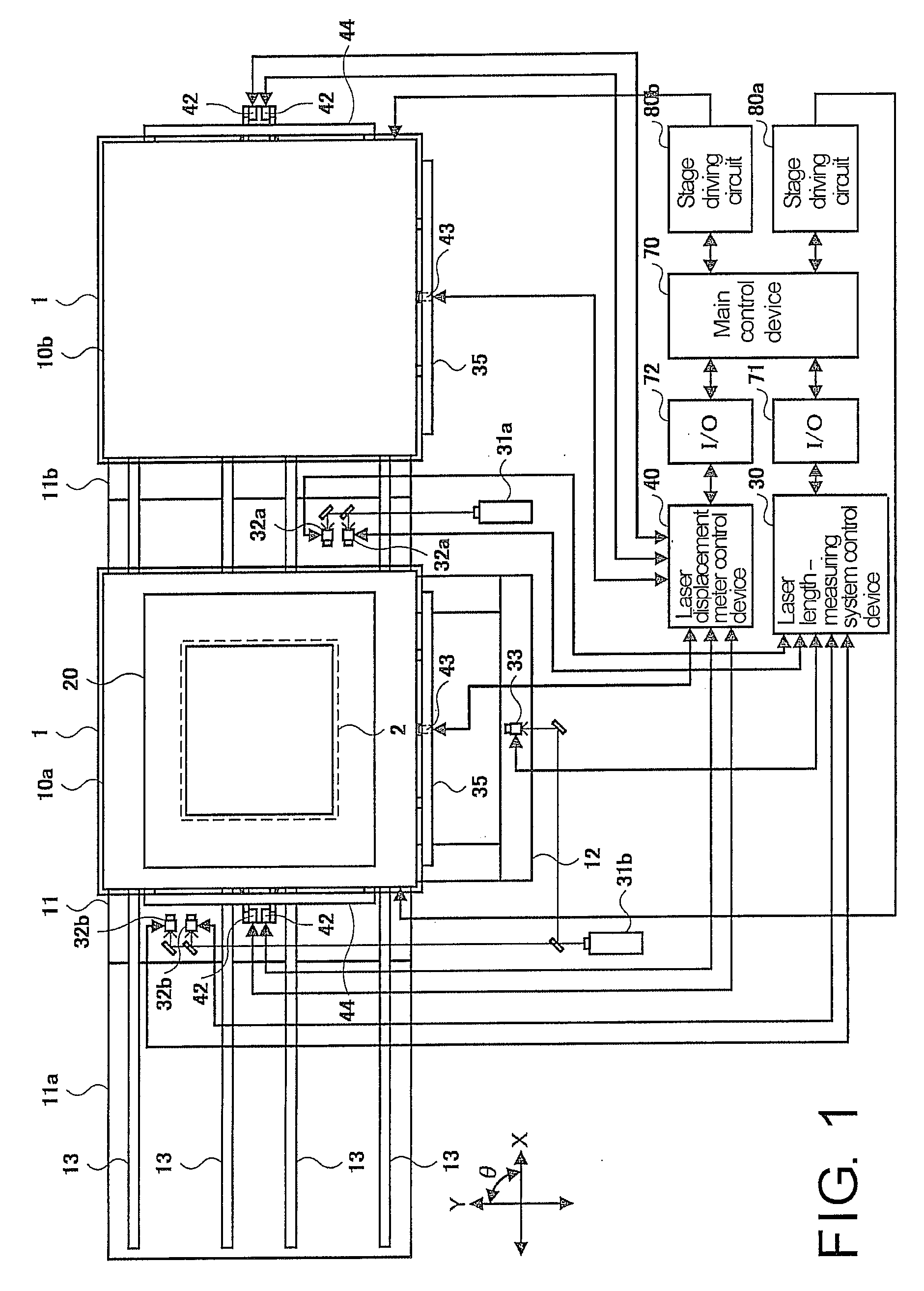
[0037]FIG. 1 is a schematic view of an exposure apparatus according to an embodiment of the present invention. Referring to FIG. 1, the exposure apparatus includes a plurality of chucks 10a and 10b, a primary stage base 11, a plurality of secondary stage bases 11a and 11b, a stage 12, X guide rails 13, a plurality of movable stages, a mask holder 20, a laser length-measuring system control device 30, a plurality of first laser length-measuring systems, a second laser length-measuring system, a laser displacement meter control device 40, laser displacement meters 42 and 43, bar mirrors 44 and 45, a main control device 70, input / output interface circuits 71 and 72, and stage driving circuits 80a and 80...


PUM


Abstract

The movable stages carry chucks 10a and 10b and move towards secondary stage bases 11a and 11b and a primary stage base 11, thereby positioning the substrate 1 on the primary stage base 11. Each first laser length-measuring system includes laser sources 31a and 31b, bar mirrors 34a and 34b mounted below X stages 14 of the movable stages, and laser interferometers 32a and 32b disposed at positions deviated from X guide rails 13 on the primary stage base 11, so as to detect positions of the movable stages in X direction. The laser interferometers 32a and 32b will not be influenced by the vibration of the secondary stage bases 11a and 11b. Meanwhile, the measuring distance from the laser interferometers 32a and 32b to the movable stages on the primary stage base 11 is reduced.

Description

CROSS-REFERENCE TO RELATED APPLICATION[0001]This application claims the priority benefit of Japan application serial no. 2007-197332, filed Jul. 30, 2007. All disclosure of the Japan application is incorporated herein by reference.BACKGROUND OF THE INVENTION[0002]1. Field of the Invention[0003]The present invention relates to an exposure apparatus and an exposure method using a proximity mode for exposing a substrate in manufacturing a display panel substrate of a liquid crystal display device and the like, and a method for manufacturing the display panel substrate using the same. More particularly, the present invention relates to an exposure apparatus including a plurality of movable stages, an exposure method, and a method for manufacturing the display panel substrate using the same.[0004]2. Description of Related Art[0005]The thin film transistor (TFT) substrates, color filter substrates, plasma display panel substrates, organic electroluminescence (EL) display panel substrates,...

Claims


Application Information

Patent Timeline
IPC IPC(8): G03B27/42G03B27/58
CPCG03F7/7035G03F7/70775G03F7/70733
Inventor MATSUYAMA, KATSUAKINEMOTO, RYOHJIMORI, JUNICHISATO, RYUGOHAYASHI, TOMOAKI
Owner HITACHI HIGH-TECH CORP
Why Eureka
Try Eureka