Plasma display apparatus

a technology of display apparatus and plasma, which is applied in the direction of electrical apparatus casing/cabinet/drawer, identification means, instruments, etc., can solve the problems of low dissipation effect of thermal grease, complex process for applying thermal grease, and low thermal dissipation efficiency of tcp as compared with cof, so as to reduce vibration, improve heat dissipation, and reduce noise

Inactive Publication Date: 2009-02-05
SAMSUNG SDI CO LTD
View PDF0 Cites 5 Cited by
  • Summary
  • Abstract
  • Description
  • Claims
  • Application Information

AI Technical Summary

Benefits of technology

[0013]It is another object to provide a plasma display apparatus that exhibits improved heat dissipation, reduced vibration, and diminished noise.
[0014]It is still another object to provide a plasma display apparatus that is amenable to manufacture in reduced time and at lower cost per unit.
[0015]Exemplary embodiments provide a plasma display apparatus that is configured to improve a thermal dissipation effect of a driver integrate circuit and simplify a manufacturing process by directly applying thermal conductive silicone on the front and rear surfaces of the driver integrated circuit.
[0016]Exemplary embodiments also provide a plasma display apparatus that can reduce vibration and noise generated on a PDP by applying thermal conductive silicone on the front and rear surfaces of the driver integrated circuit.

Problems solved by technology

However, since the driver integrated circuit of the TCP is small and no thermal dissipation mechanism is provided, the TCP has lower thermal dissipation efficiency as compared with the COF.
However, the thermal dissipation effect of the thermal dissipation pad is slight and a process for applying the thermal grease is complicated.
Therefore, the overall manufacturing process is longer, more complex, time consuming and expensive.

Method used


Image

  • Plasma display apparatus
  • Plasma display apparatus
  • Plasma display apparatus

Examples


Embodiment Construction

[0033]The present invention will be described more fully hereinafter with reference to the accompanying drawings, in which exemplary embodiments of the invention are shown. Like reference numerals designate like elements throughout the specification. Further, the drawings and description are to be regarded as illustrative in nature and not restrictive.

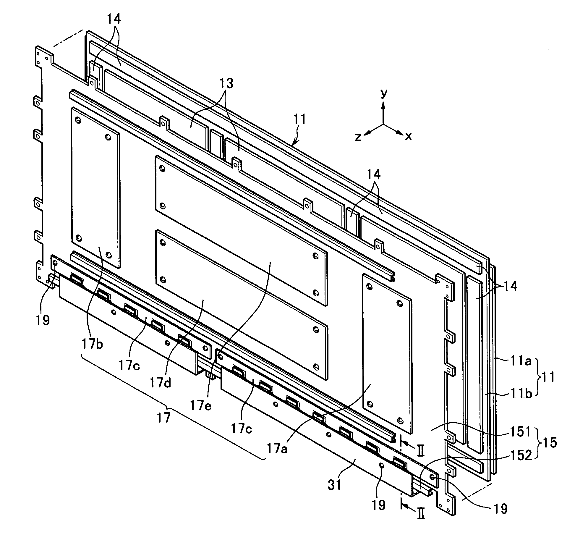
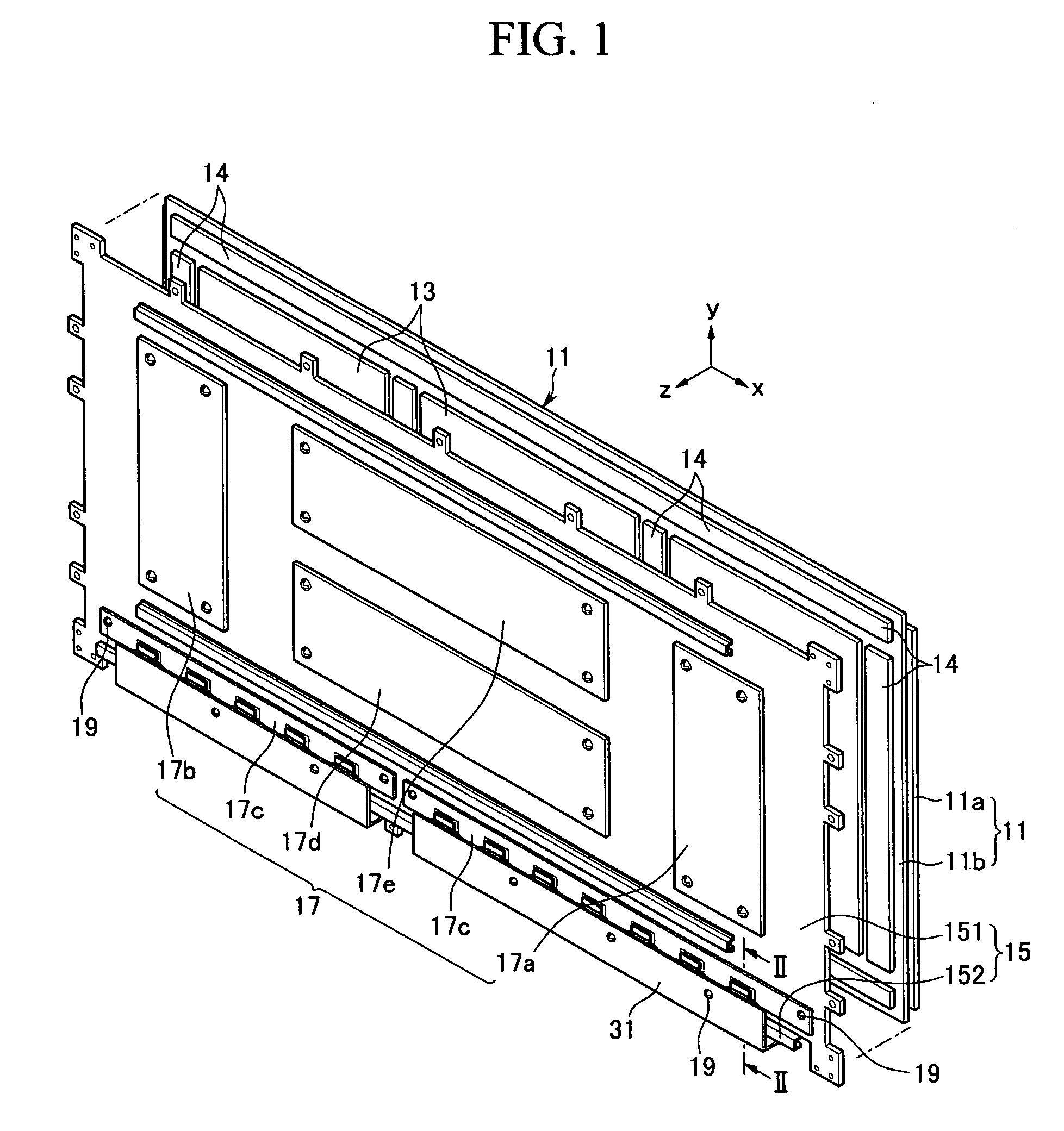
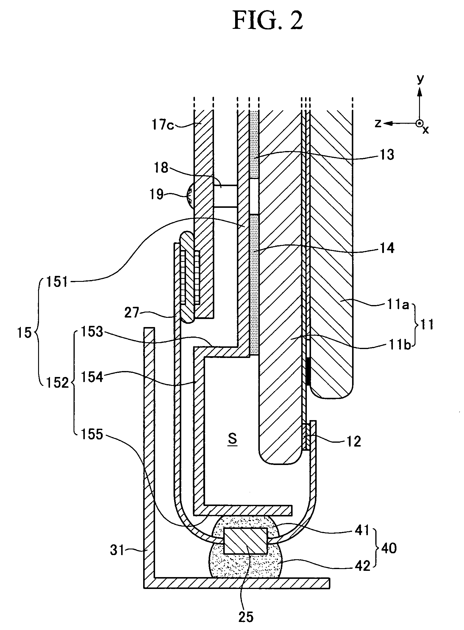
[0034]FIG. 1 is an exploded perspective view of a plasma display apparatus according to a first exemplary embodiment of the present invention, and FIG. 2 is a sectional view taken along line II-II of FIG. 1.

[0035]Referring to FIGS. 1 and 2, a plasma display apparatus of a first exemplary embodiment of the present invention includes a PDP 11, a plurality of thermal dissipation sheets 13, a chassis base 15, and a printed circuit board assembly (PBA) 17.

[0036]The PDP 11 includes front and rear substrates 11a and 11b. The PDP 11 displays an image using gas discharge occurring in a space defined between the front and rear substrates 11a and...


PUM


Abstract

A plasma display apparatus that includes a plasma display panel, a chassis base, a driving circuit, a flexible printed circuit, a driver integrated circuit and a first and second thermal conductive silicone. The chassis base is provided at a side of the plasma display panel. The driving circuit unit is provided at a side of the chassis base. The flexible printed circuit electrically connects an electrode of the plasma display panel to the driving circuit unit. The driver integrated circuit is connected to the flexible printed circuit. The first thermal conductive silicone is provided between the driver integrated circuit and the chassis base. The second thermal conductive silicone is provided, in another embodiment, between the driver integrated circuit and the chassis base and encloses an extending portion of the driver integrated circuit. The first and second thermal conductive silicone dissipate heat, absorb vibrations and reduce noise.

Description

CLAIM OF PRIORITY[0001]This application makes reference to, incorporates the same herein, and claims all benefits accruing under 35 U.S.C. §119 from an application earlier filed in the Korean Intellectual Property Office on Aug. 2, 2007 and there duly assigned Serial No. 10-2007-0077726.BACKGROUND OF THE INVENTION[0002]1. Field of the Invention[0003]The present invention relates to a plasma display apparatus and, more particularly, to a plasma display apparatus that is designed to improve thermal dissipation efficiency, simplify a manufacturing process, and reduce noise by enclosing a driver integrated circuit with silicone.[0004]2. Description of the Related Art[0005]A plasma display apparatus is configured to display an image on a plasma display panel (PDP) using plasma generated by gas discharge. In the plasma display apparatus, electrodes of the PDP are electrically connected to a drive circuit unit through a flexible printed circuit (FPC). A driver integrated circuit is formed ...

Claims


Application Information

Patent Timeline
Patent Type & Authority Applications(United States)
IPC IPC(8): H05K7/14G09F9/00
CPCH05K7/20963H01J11/46H01J17/28
Inventor CHOI, JIN-SEEKHWANG, HUI-YUNLEE, IK-SANG
Owner SAMSUNG SDI CO LTD
Why Eureka
Try Eureka