
Object lens, optical pickup, and optical disc device

a technology of optical discs and objects, applied in the field of objects lenses, optical pickups, optical disc devices, can solve the problems of optical pickups, deterioration in the quality of played signals, and increased cost and size of optical pickups, and achieve excellent recording and/or playing signals, without complicated structure

Active Publication Date: 2009-02-05
SONY CORP
View PDF4 Cites 14 Cited by
  • Summary
  • Abstract
  • Description
  • Claims
  • Application Information

AI Technical Summary

Benefits of technology

[0021]According to the above configurations, due to a diffraction unit provided on one face of an optical element disposed on an optical path between an emitting unit emitting optical beams and the signal recording face of an optical disc, optical beams corresponding to each of thee types of optical discs having different usage wavelengths can be suitably condensed on the signal recording faces thereof with a single shared object lens, thereby realizing three-wavelength compatibility with a common object lens, and realizing excellent recording and / or playing of signals to and from each optical disc, without a complicated structure.

Problems solved by technology

However, optical pickups according to the related art such as described above have the following problems.
First, each optical disc has a different optimal inclination of object lens, and with the above-described optical pickup, using two object lenses 433 and 434 means that the attachment angle of the actuator of the object lenses 433 and 434 to lens holders may be unsuitable, resulting in a situation wherein an optimal object lens inclination cannot be realized as to an optical disc, resulting in deterioration in quality of played signals.
Also, with the above-described optical pickup, increase in the number of parts which need to be placed along the optical path of each of the two optical systems, such as redirecting mirrors, collimator lenses, quarter-wave plates, and so on, is necessitated due to using the two object lenses 433 and 434, causing the problem of increased cost and increased size of the optical pickup.
However, each of these configurations have the lens units, diffraction units, liquid crystal devices, etc., individually formed and then later assembled, meaning that a rather high level of precision is necessary for positioning these and adhering multiple diffraction faces, leading to more and increasingly troublesome and complicated steps in manufacturing, and problems of failure to meet the necessary precision.
Also, for example, there has been proposed in Japanese Unexamined Patent Application Publication No. 2004-265573 an optical pickup wherein a diffraction unit is provided on the entire face, but this has only been successful in realizing compatibility of two wavelengths.
In order to realize compatibility of three wavelengths, there is the need to separately provide an object lens corresponding to the other wavelength, and increase in the number of optical parts, and accordingly increased complication of the arrangement, has been a problem.

Method used


Image

  • Object lens, optical pickup, and optical disc device
  • Object lens, optical pickup, and optical disc device
  • Object lens, optical pickup, and optical disc device

Examples


first embodiment

First Embodiment of Optical Pickup (FIGS. 2 through 19)

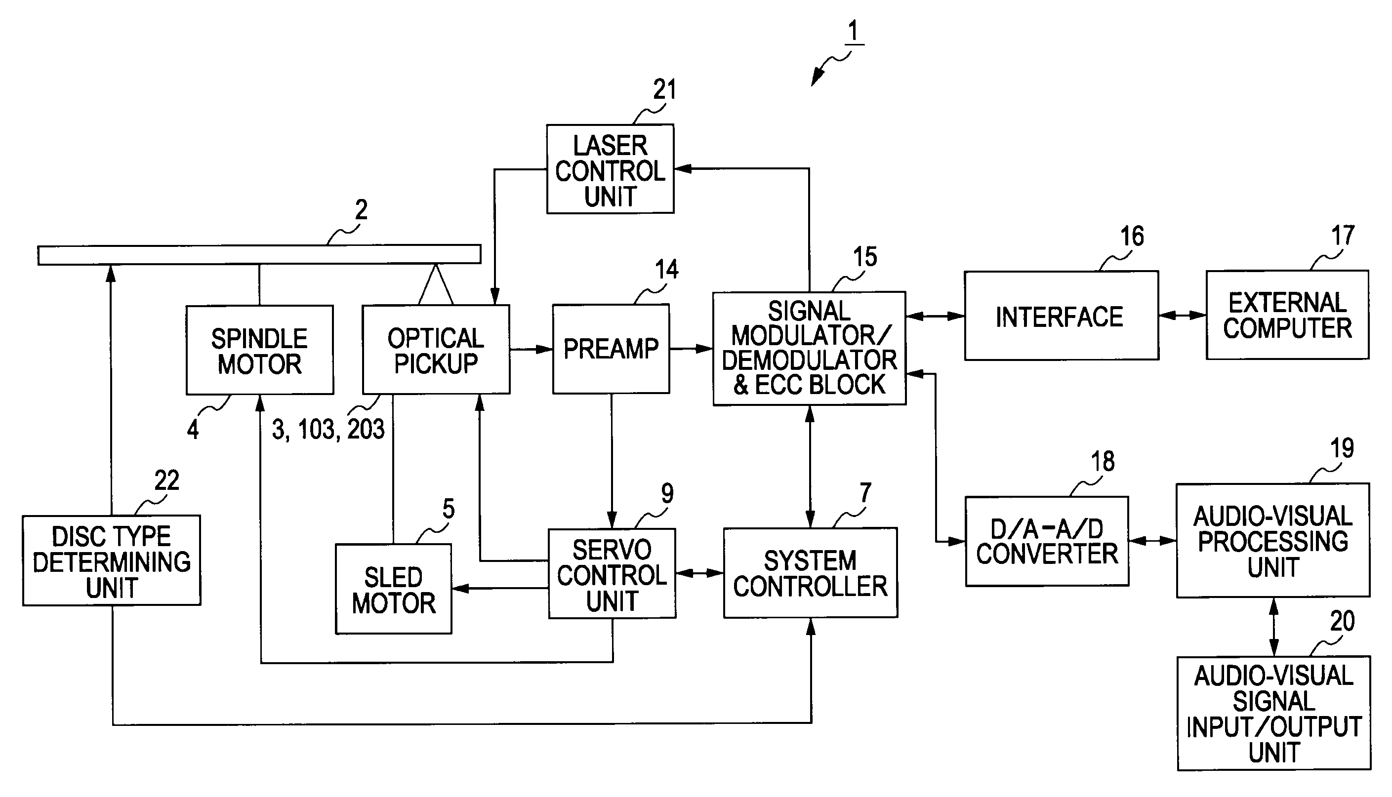
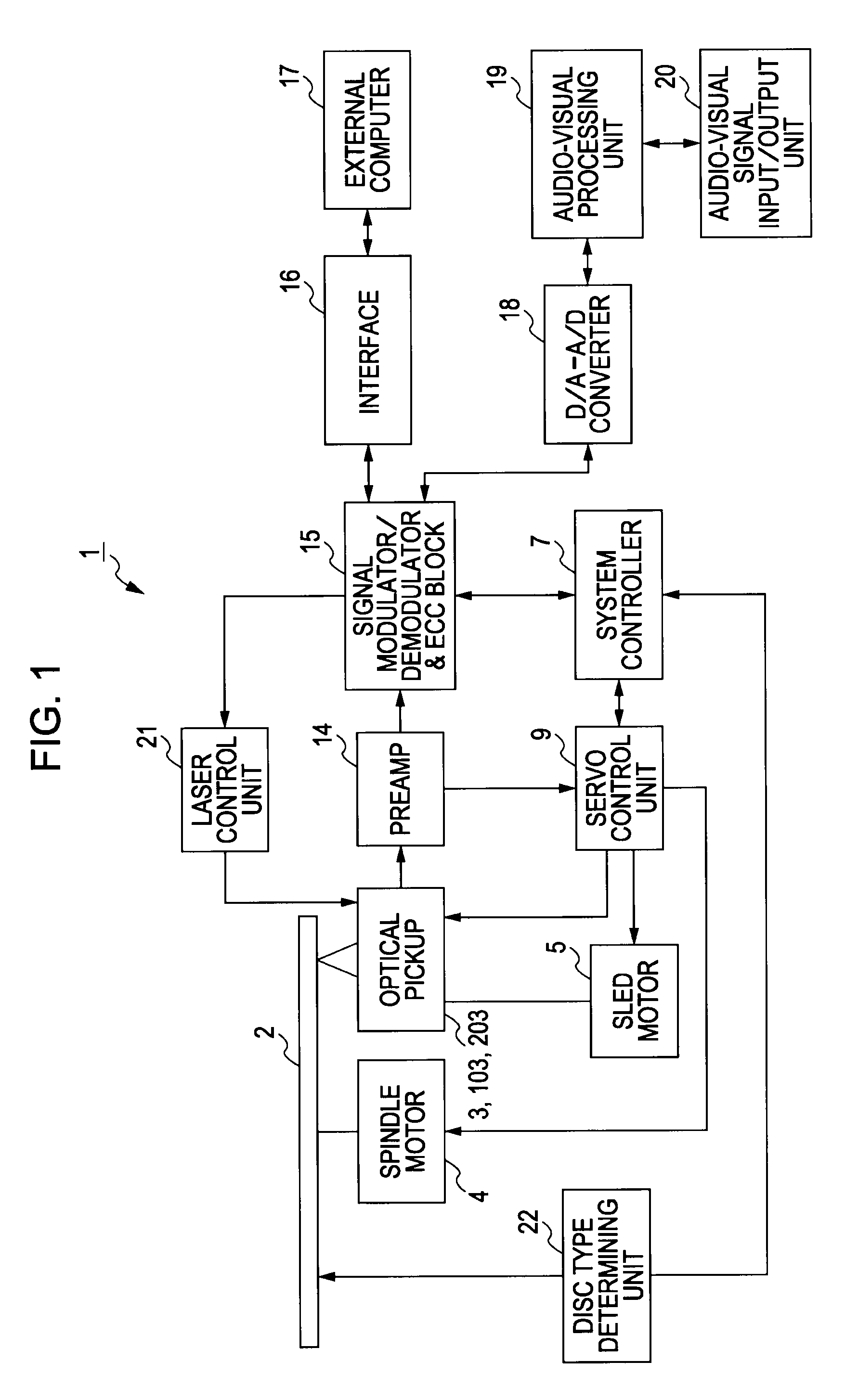
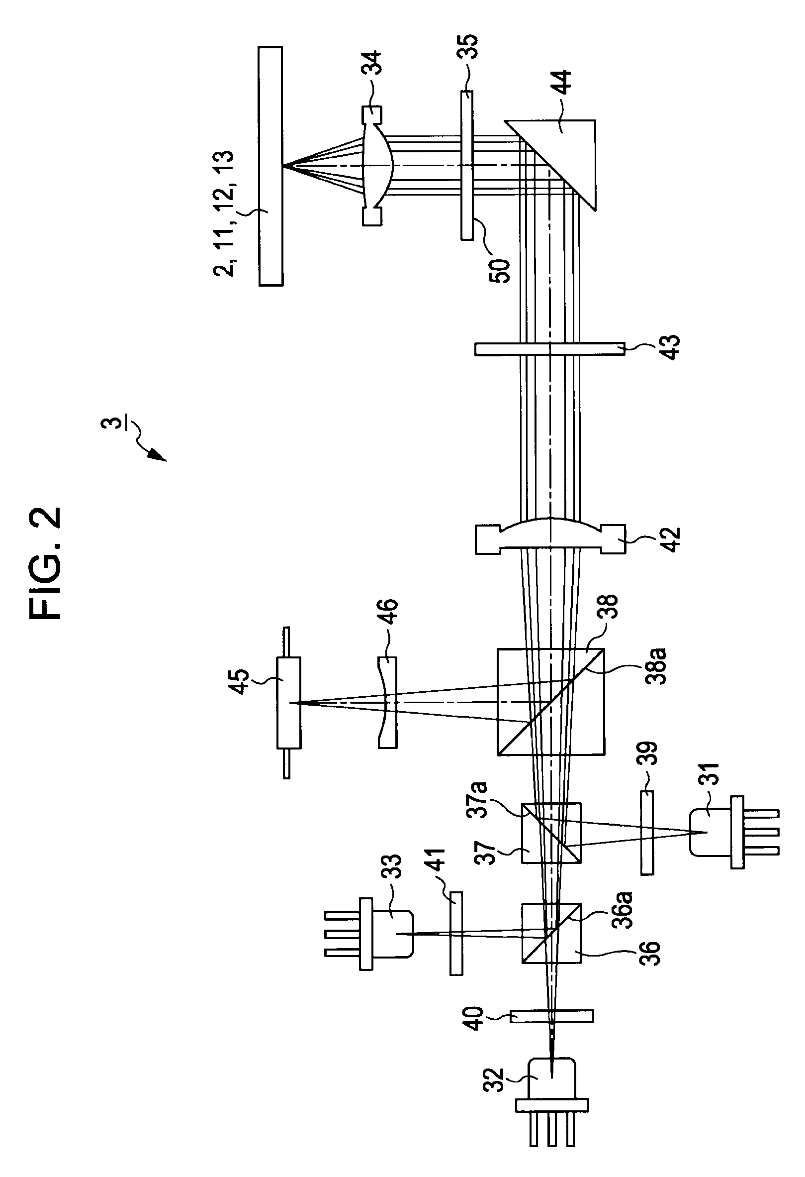
[0102]First, an optical pickup 3 to which the present invention is applied will be described as a first embodiment of the optical pickup according to the present invention, with reference to FIGS. 2 through 19. As described above, the optical pickup 3 is an optical pickup which selectively irradiates multiple optical beams with different wavelengths onto three types of optical discs arbitrarily selected from first through third optical discs 11, 12, and 13, of which the format such as the thickness of the protective layer differs, thereby performing recording and / or playing of information signals.

[0103]As shown in FIG. 2, the optical pickup 3 to which the present invention has been applied includes a first light source 31 having a first emitting unit for emitting an optical beam of a first wavelength, a second light source 32 having a second emitting unit for emitting an optical beam of a second wavelength longer than the first...

second embodiment

Second Embodiment of Optical Pickup (FIGS. 20 Through 36)

[0210]Next, an optical pickup 103 to which the present invention is applied will be described as a second embodiment of the optical pickup used in the above-described optical disc device 1, with reference to FIGS. 20 through 36. As described above, the optical pickup 103 is an optical pickup which selectively irradiates multiple optical beams with different wavelengths onto optical discs arbitrarily selected from first through third optical discs 11, 12, and 13, of which the format such as the thickness of the protective layer differs, thereby performing recording and / or playing of information signals.

[0211]As shown in FIG. 20, the optical pickup to which the present invention has been applied includes a first light source 131 having a first emitting unit for emitting an optical beam of a first wavelength, a second light source 132 having a second emitting unit for emitting an optical beam of a second wavelength longer than th...

third embodiment

Third Embodiment of Optical Pickup (FIGS. 37 through 59)

[0355]Next, an optical pickup 203 to which the present invention is applied will be described in detail as a third embodiment of the optical pickup used in the above-described optical disc device 1, with reference to FIGS. 37 through 59. As described above, the optical pickup 203 is an optical pickup which selectively irradiates multiple optical beams onto optical discs selected from first through third optical discs 11, 12, and 13, of which the format such as the thickness of the protective layer differs, thereby performing recording and / or playing of information signals.

[0356]Note that the optical pickup 203 serving as the third embodiment described here is for solving the same problems as those of the above-mentioned optical pickups 3 and 103, and additionally, solving the following problems, and includes an arrangement for obtaining more advantageous effects. Firstly, with the optical pickup 203, demands for realizing enhan...


PUM


Abstract

An optical pickup includes: a first emitting unit to emit an optical beam of a first wavelength; a second emitting unit to emit an optical beam of a second wavelength; a third emitting unit to emit an optical beam of a third wavelength; an object lens to condense optical beams emitted from the first through third emitting units onto a signal recording face of an optical disc; and a diffraction unit provided on one face of an optical element or the object lens positioned on the optical path of the optical beams of the first through third wavelengths; wherein the diffraction unit includes a generally circular first diffraction region provided on the innermost perimeter, a ring zone shaped second diffraction region provided on the outer side of the first diffraction region, and a ring zone shaped third diffraction region provided on the outer side of the second diffraction region.

Description

CROSS REFERENCES TO RELATED APPLICATIONS[0001]The present invention contains subject matter related to Japanese Patent Application JP 2007-197961 filed in the Japanese Patent Office on Jul. 30, 2007, Japanese Patent Application JP 2008-063383 filed in the Japanese Patent Office on Mar. 12, 2008, and Japanese Patent Application JP 2007-303610 filed in the Japanese Patent Office on Nov. 22, 2007, the entire contents of which are incorporated herein by reference.BACKGROUND OF THE INVENTION[0002]1. Field of the Invention[0003]The present invention relates to an object lens used with an optical pickup for recording and / or playing information signals to and / or from three different types of optical discs, the optical pickup, and an optical disc device using the optical pickup.[0004]2. Description of the Related Art[0005]As of recent, there has been proposed, as a next-generation optical disc format, an optical disc capable of high density recording, wherein signals are recorded and played ...

Claims


Application Information

Patent Timeline
IPC IPC(8): G11B7/00G11B7/1353G11B7/1374
CPCG11B7/1275G11B2007/0006G11B7/1374G11B7/1353
Inventor KANEDA, KAZUMASAASOMA, YOSHITOYASUI, TOSHIFUMITAKAHASHI, KAZUYUKI
Owner SONY CORP
Features
  • Generate Ideas
  • Intellectual Property
  • Life Sciences
  • Materials
  • Tech Scout
  • Unparalleled Data Quality
  • Higher Quality Content
  • 60% Fewer Hallucinations
Learn More