
Carbon nanofibers and procedure for obtaining said nanofibers

Active Publication Date: 2009-02-05
GRUPO ANTOLIN ING
View PDF1 Cites 38 Cited by
  • Summary
  • Abstract
  • Description
  • Claims
  • Application Information

AI Technical Summary

Benefits of technology

[0004]The procedure for obtaining the carbon nanofibers is characterized by the use of a specific metallic catalyst and production parameters that allow establishing binary phase conditions in said catalyst which, combined with the chemical composition of the furnace atmosphere and the fluidodynamic conditions verified inside the production furnace, provide a growth of the carbon nanofibers faster than the corresponding to the standard production processes known for carbon nanofibers, resulting in a higher quality of the carbon nanofibers.
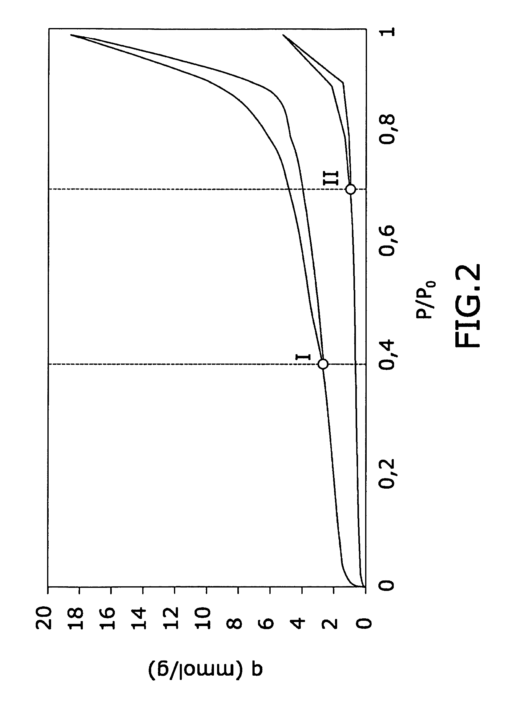
[0005]This higher quality of the carbon nanofibers this way obtained is reflected on their surface, where the accumulation of amorphous carbon of pyrolytic origin is negligible, in contrast with other carbon nanofibers of the state of the art. Consequently, the specific surface area is greater, the graphitization degree is higher and the specific volume of mesopores is higher too. It is therefore observed that their gas adsorption capacity due to the mesopores volume is considerably higher than that provided by other carbon nanofibers.

Problems solved by technology

The production process used to manufacture the carbon nanofibers is crucial from an industrial point of view, since the different conditions valid for obtaining carbon nanofibers in the laboratory may not be feasible from an industrial standpoint due to the limited manufacturing capacity.
Amorphous carbon has negative effects on the surface activity of the nanofiber, as will be commented further below, and therefore also has negative effects on its possible applications.
The carbon nanofiber thickening process due to the deposition of amorphous carbon of pyrolytic origin is very difficult to avoid, due to the fact that the deposition of pyrolytic amorphous carbon on the carbon nanofiber surface takes place very quickly at production conditions on a floating catalyst system.
The structure of carbon nanofibers is often modelled by one of these configurations, although in most cases it is difficult to precisely determine the actual structure due to the limitations of the inspection and analysis instruments.
In this case the fiber will have a poorer quality and fewer applications.
The characteristic furnace length [L0] is mainly constrained by constructive limitations derived from limited features of the materials currently available for manufacturing such kind of furnaces.
The need for a high [L0] would lead to a greater size of the furnace that can make its construction unfeasible.
Current techniques of making this hind of furnaces do not allow exceeding certain size of the furnace.
However the circulation velocity cannot be increased arbitrarily.

Method used


Image

  • Carbon nanofibers and procedure for obtaining said nanofibers
  • Carbon nanofibers and procedure for obtaining said nanofibers
  • Carbon nanofibers and procedure for obtaining said nanofibers

Examples


Embodiment Construction

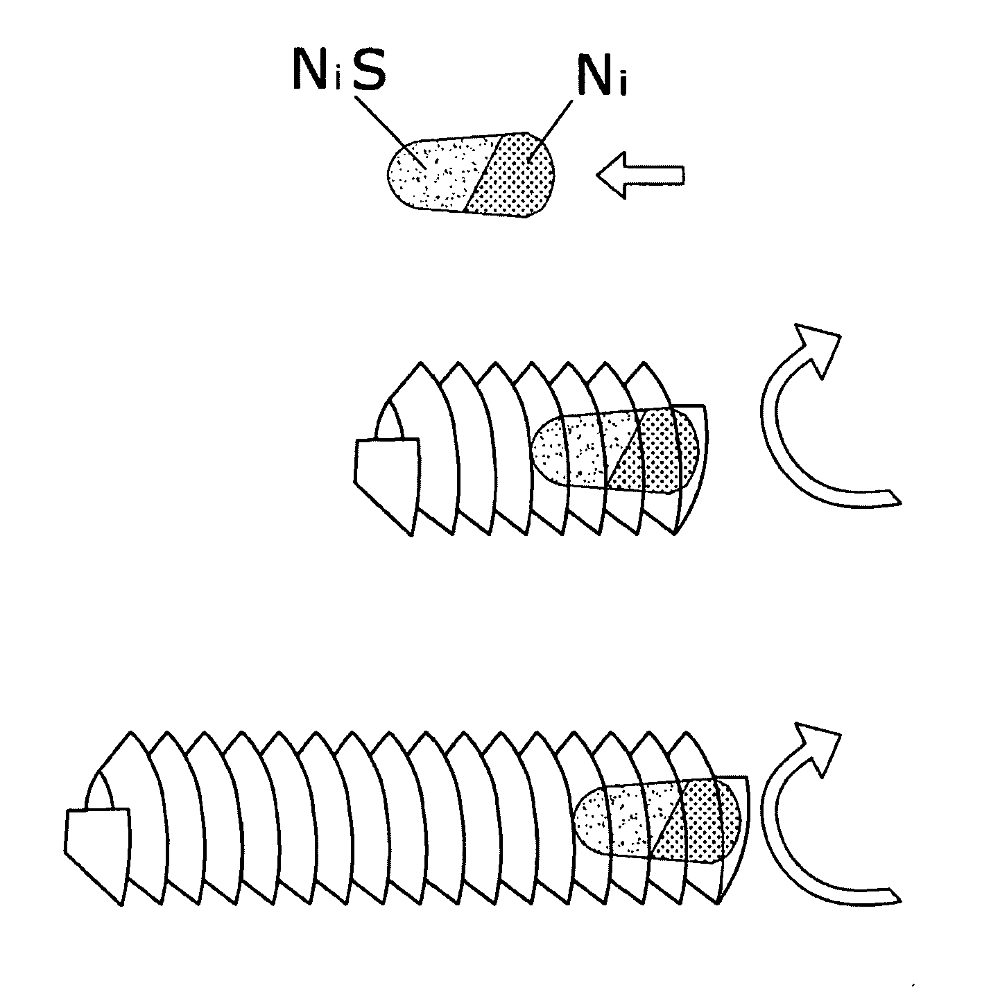
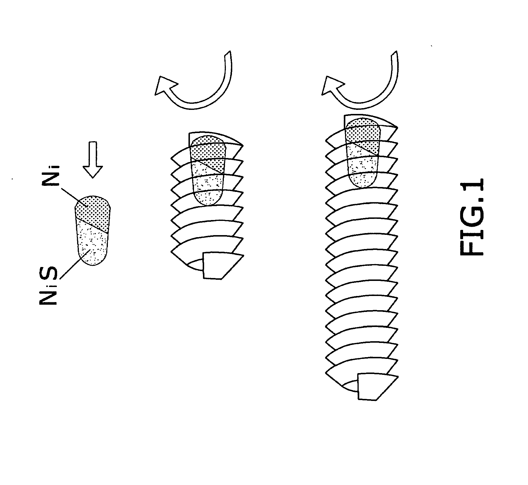
[0037]The carbon nanofibers object of the invention presents a hollow structure with a circular cross-section. It is formed by graphitic planes arranged in the form of spirally superimposed ribbons along the axis of the carbon nanofibers thereby ensuring its continuity, so that among its noteworthy properties are its high electric and thermal conductivities. This structure will be shown in the drawings and the electron microscopy pictures of the detailed description of the invention.

[0038]The carbon nanofiber surface presents two families of free edges able to form bonds with other substances: those facing the outside of the nanofiber and those facing the inner cylindrical channel of the carbon nanofiber.

[0039]Although most the carbon nanofibers obtained by the manufacturing process of the invention present a structure corresponding to a spirally superimposed ribbon model, it is noted that other kind of structures are also present as a smaller part of the final product, such as plat...


PUM

PropertyMeasurementUnit
Temperatureaaaaaaaaaa

Abstract

The object of the present invention is carbon nanofibers mainly characterized by their high specific volume of mesopores, their high gas adsorption capacity and presenting a graphitic hollow structure. A second object of this invention is a procedure for obtaining such carbon nanofibers, which makes use of a metallic nickel catalyst and specific process furnace parameters that combined with the chemical composition of the furnace atmosphere and the fluidodynamic conditions of the gas stream inside the furnace, result in a faster growth of the carbon nanofibers and also in a higher quality of the carbon nanofibers obtained.

Description

OBJECT OF THE INVENTION[0001]The object of the present invention are carbon nanofibers that present improved physical properties that allow their use in a wide range of applications as well as in fields in which the use of carbon nanofibers obtained by other procedures is less effective.[0002]These carbon nanofibers are defined mainly by macroscopic properties that characterize their performance. The most relevant property is the specific volume of mesopores, which is related to the structural configuration determined by hollow graphitic filament with a large inner diameter and by high gas adsorption capacity.[0003]Other object of this invention is a procedure for obtaining said carbon nanofibers developed in order to make possible the mass production for industrial applications and with properties such as a high specific surface area and a high graphitization degree, obtained without requiring any carbon nanofiber post-treatment. These improved properties prove the high quality of ...

Claims


Application Information

Patent Timeline
IPC IPC(8): D01F9/12D01F9/127B32B5/02
CPCB82Y30/00Y10S977/735C01B31/0233D01F9/127Y10T428/2918Y10T428/2913Y10T428/2935Y10T428/29Y10T428/2973Y10T428/2975Y10T428/298Y10S977/734Y10S977/762Y10S977/765B82Y40/00C01B32/162
Inventor GONZALEZ MORAL, JOSE LUISVERA AGULLO, JOSEMERINO SANCHEZ, CESARMARTIN GULLON, IGNACIO
Owner GRUPO ANTOLIN ING
Learn More