
Method of decoding content data blocks, corresponding computer program product and decoding device

a content data and block technology, applied in the direction of code conversion, error correction/detection using convolutional codes, code transmission, etc., can solve the problems of low efficiency, high bit rate brought into play, and inability to maintain efficiency, so as to minimize processing time, consumption of resources and energy, and cost little in terms of resources and energy

Active Publication Date: 2009-02-05
CANON KK
View PDF21 Cites 4 Cited by
  • Summary
  • Abstract
  • Description
  • Claims
  • Application Information

AI Technical Summary

Benefits of technology

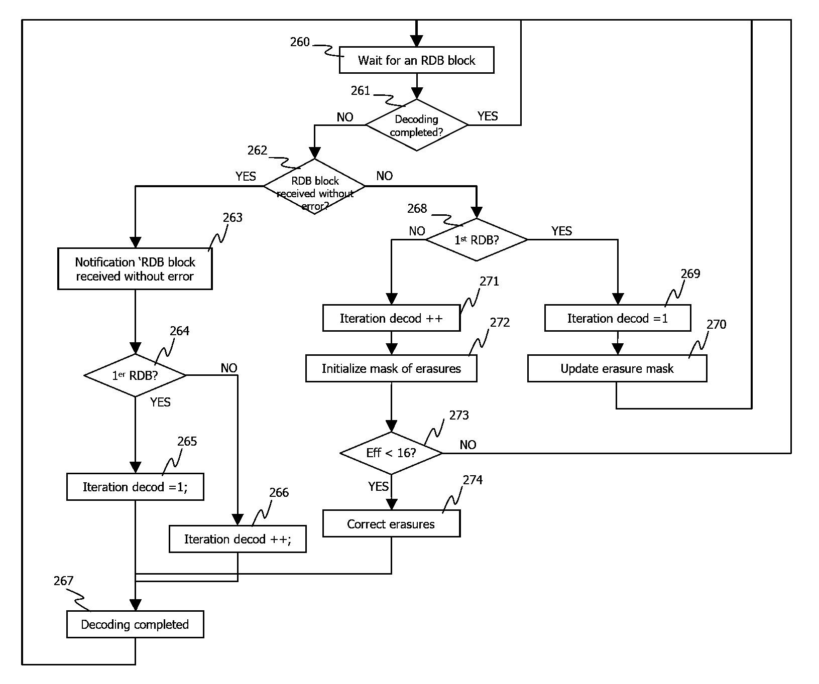
[0031]Thus, when the conditions of broadcasting of the content in the communications network are ideal (for example with an absence of shadowing), the invention enables the activation of a first determining of erasures from a set of data blocks supposed to rapidly lead to full decoding in order to retrieve all the initially sent symbols. Thus, in this case, the error correction is essentially accomplished by means of a decoding, performed from a first determining of errors, that is simple and costs little in terms of resources and energy. This minimizes the processing time and hence the consumption of resources and energy by the decoding node.
[0041]Thus, it is possible to carry out a first determining of erasures from three data blocks representing a same set of symbols extracted from a content, in making for example a two-by-two comparison of the symbols, and to carry out a second determining of erasures from the four data blocks should the number of erasures determined by the first determining of erasures be greater than the given threshold. This therefore provides, with high probability, for the first determining of erasures to be sufficient for the success of the decoding when there is no shadowing during the transmission of the data blocks of the first selection.
[0043]For example, this topology, illustrated by a reception graph, takes account of at least one obstacle to communication between two nodes, in the communications network, thus making it possible to have a synchronous bandwidth distribution matrix describing retransmissions of data blocks for decoding nodes, preventing permanent shadowing.
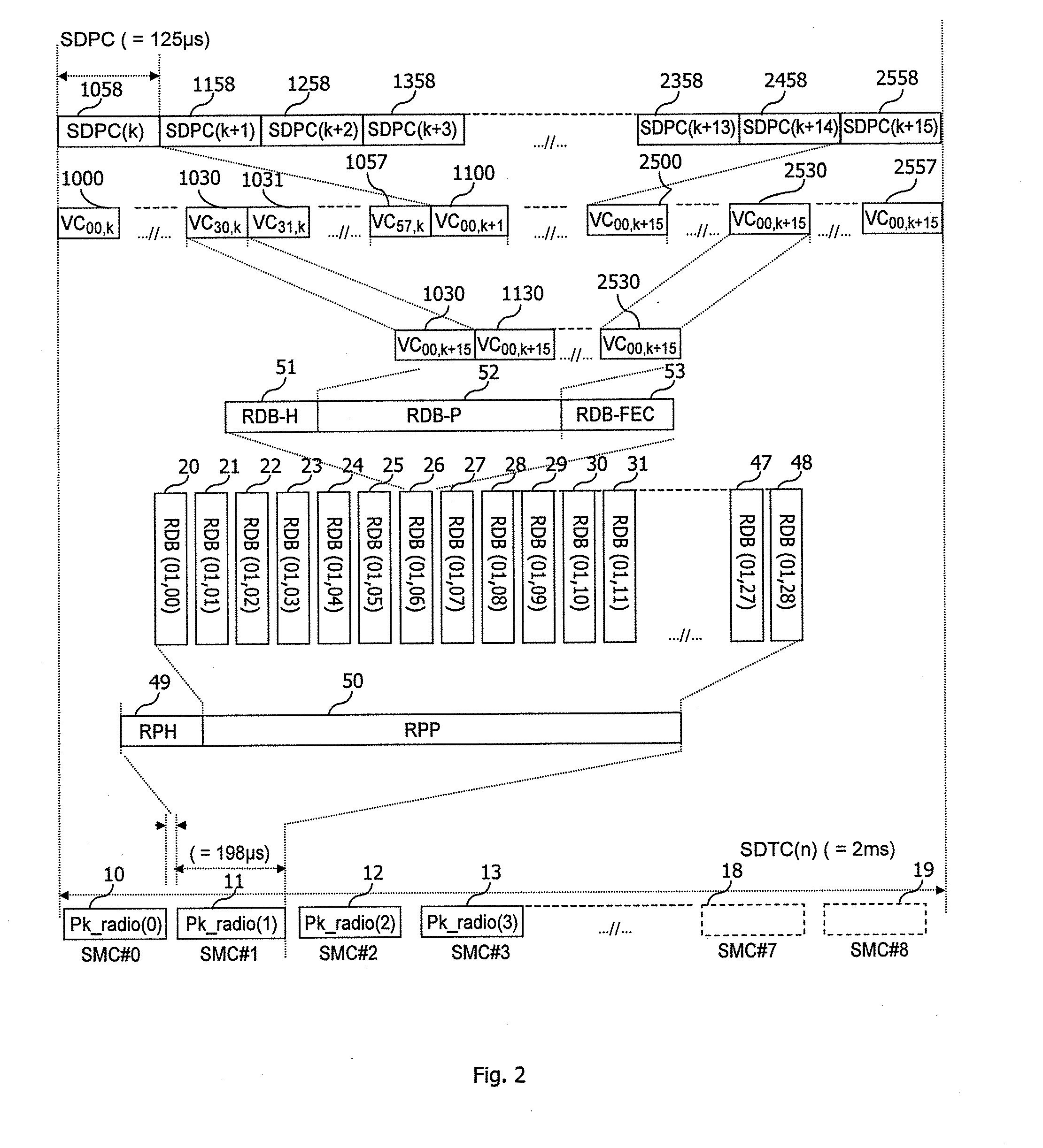
[0047]Thus, the decoding by erasure jointly uses the multiple transmissions of a data block and the Reed Solomon type redundancy information associated with this data block (as presented with reference to FIG. 2 described here below), making it possible to reduce the number of symbols representing this redundancy information, without affecting the decoding capacity. Thus, the efficiency of the code is improved and therefore the use of the synchronous bandwidth to permit, for example, up to two additional data blocks per row of a synchronous bandwidth distribution matrix (as illustrated here below with reference to FIG. 5).
[0053]Thus, the interruption of the decoding performed on the basis of the second erasures makes it possible to maintain a perfect synchronization of a content broadcast in the network by a sender node so that the decoding nodes restitute the content in a synchronized way. Thus, if the content is a sound content, then spatialization effects can be implemented during the restitution of the content.

Problems solved by technology

Indeed, in this case of use, the range of transmission is limited to about ten meters but the bit rates brought into play are very high, sometimes more than one gigabit per second owing to the nature (both video and audio) of the high resolution of the information transmitted.
Consequently, one drawback of these first MIMO error correction techniques is that they are not suited to remaining efficient during the occurrence of an unexpected modification (modification outside the framework of the characteristics of the transmission channel defined a priori) of the transmission conditions (for example the appearance of an obstacle on the transmission path causing a shadowing on the transmission path) in the communications network.
Furthermore, another drawback of these first techniques is that they rely on the reduction of the error rate in the data symbols received rather then the correction of errors within these same symbols.
Again, one drawback of these second error correction techniques relies on the fact that it cannot be used to pursue an efficient error correction process when there is an unexpected deterioration (caused for example by the appearance of an obstacle on the transmission path causing a shadowing on the transmission path) of the conditions of transmission in the network.

Method used


Image

  • Method of decoding content data blocks, corresponding computer program product and decoding device
  • Method of decoding content data blocks, corresponding computer program product and decoding device
  • Method of decoding content data blocks, corresponding computer program product and decoding device

Examples


Embodiment Construction

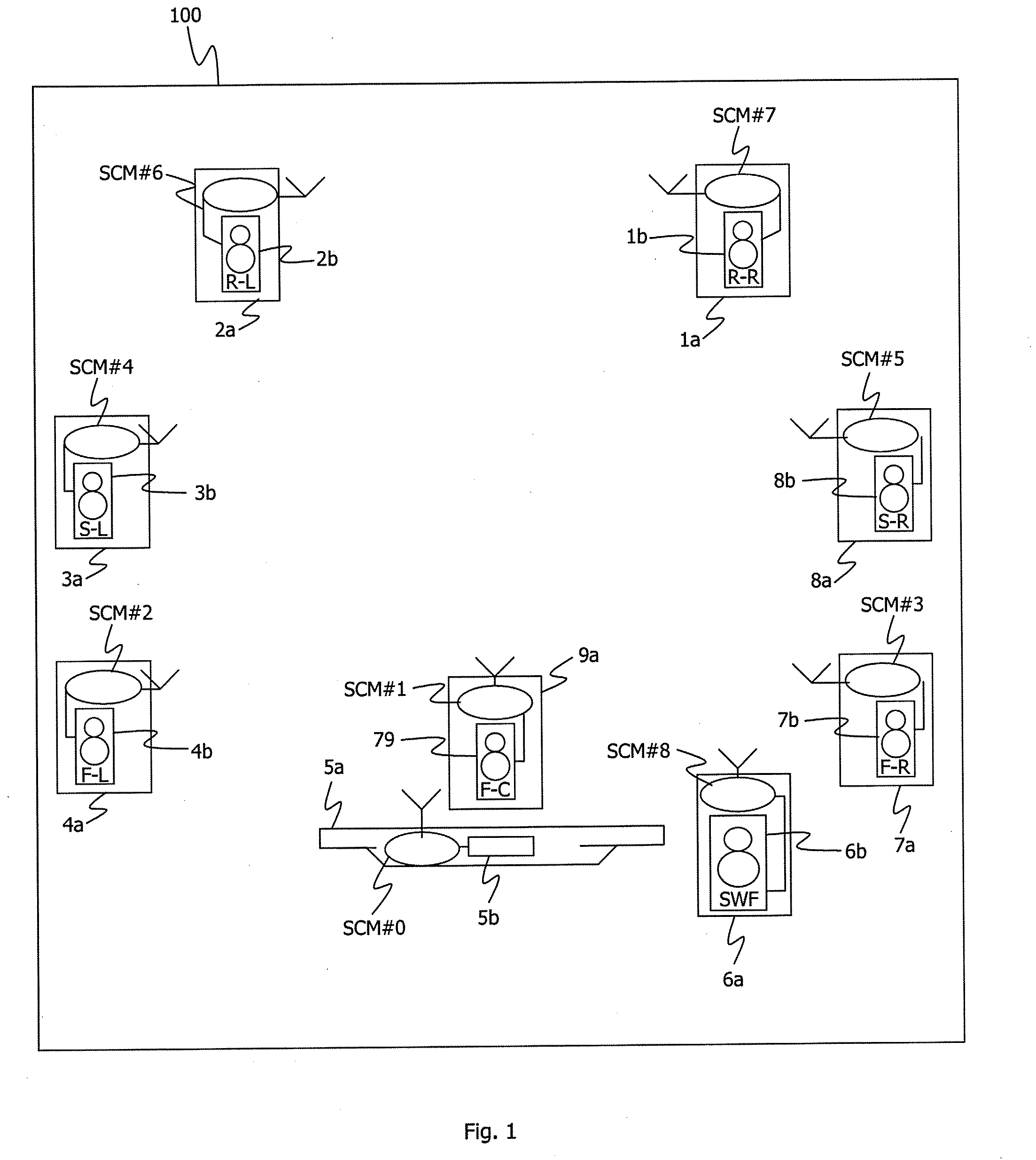
[0090]The description of a particular application of the decoding method according to a particular embodiment of the invention is situated here below in the context of a communications network 100 which is a 7.1 type home cinema network as illustrated in FIG. 1.

[0091]Naturally, the invention can also be applied in the context of a 5.1 type home cinema or even in any other communications network.

[0092]For example, the home cinema network 100 comprises:[0093]A WAD (“Wireless Audio Decoder”) node referenced 5a which is for example a flat-screen television set. The WAD 5a comprises a multiple-channel audio decoder or “surround sound decoder”) referenced 5b. The decoder 5b is capable of broadcasting on the different audio channels associated with the audio-video content displayed on the flat screen in a way that is perfectly synchronized in the communications network 100. Preferably, the WAD node 5a also comprises an audio-video source terminal (for example in DVD player not shown);[0094...


PUM


Abstract

It is proposed a method of decoding a set of symbols to be decoded, several data blocks representative of the set of symbols to be decoded being received by a decoding node of a communications network. The data blocks are encoded by means of an error correction code enabling a decoding by erasure. The decoding node performs the following steps: a first selecting step of selecting at least one of the data blocks, a first determining step of determining first erasures, a checking step of checking whether the number of the first erasures is below a given threshold. In the event of positive determining, the decoding node performs a first decoding step of decoding by erasure of the set of symbols to be decoded. If not it performs a second selecting step of selecting at least one of the data blocks, a second determining step of determining second erasures, and a second decoding step of decoding by erasure of the set of symbols to be decoded from the second erasures.

Description

1. FIELD OF THE DISCLOSURE[0001]The field of the invention is that of the transmission of data contents in a communications network.[0002]The invention relates especially to the transmission of data contents in a synchronous wireless home communications network comprising a plurality of decoding nodes and more particularly to the transmission of contents in a 60 GHz radio transmission system.2. BACKGROUND OF THE DISCLOSURE[0003]60 GHz transmission systems are particularly well suited to the transmission of data at high bit rates on short distances. For example, a transmission system of this kind is well suited to connectivity between different elements of a home cinema. Indeed, in this case of use, the range of transmission is limited to about ten meters but the bit rates brought into play are very high, sometimes more than one gigabit per second owing to the nature (both video and audio) of the high resolution of the information transmitted.[0004]Transmission systems of this kind r...

Claims


Application Information

Patent Timeline
Patent Type & Authority Applications(United States)
IPC IPC(8): H03M13/05G06F11/07
CPCH03M13/154H03M13/23H03M13/2936H03M13/455H04S3/008H04L1/0045H04L1/0057H04L2001/0097H04R2420/07H03M13/618
Inventor FROUIN, LAURENTLE BARS, PHILIPPE
Owner CANON KK
Learn More