Wind Turbine Lightning Connection Means Method and Use Hereof

a lightning connection and wind turbine technology, applied in the installation of lighting conductors, wind energy generation, motors, etc., can solve the problems of large parts of lightning current finding alternative and often undesired and destructive routes to the ground potential, and reducing the lifespan of components. , to achieve the effect of high flexibility, high durability and high flexibility

Active Publication Date: 2009-02-12
VESTAS WIND SYST AS
View PDF2 Cites 24 Cited by
  • Summary
  • Abstract
  • Description
  • Claims
  • Application Information

AI Technical Summary

Benefits of technology

[0013]Hereby, a connection between the rotating and stationary lightning protection means is achieved which is simple in its mechanical construction and thus reliable in service. Especially, the use of no cables in order to establish the connections between the lightning connection means and the rotating and stationary lightning protection means, respectively, are advantageous in establishing a reliable system.
[0054]In an aspect of the invention, said first and second force transferring means extend angled in relation to each other from the base support part e.g. between nil and 90 degrees. A longer distance between the contact means is ensured by the mutual angling of the force transferring means. Hereby, a high degree of safety against electric sparks or arcing between the contact means is achieved.

Problems solved by technology

A problem with the above-mentioned system is the fact that the lightning current in its passage from the rotor blade to the nacelle flows via different components of the wind turbine such as the blade pitching means as well as the gear means.
The significant energy in the lightning may cause great harm to the components e.g. by arc formations and thus reduce the lifespan of the components.
Further, the means connected to the shaft has proven to be rather inefficient in removing the lightning current from the shaft.
This means that large parts of the lightning current find alternative and often undesired and destructive routes to the ground potential.
A problem with the lightning protection system of the EP patent application is the fact that the surfaces of the contacts quickly wear down and loose contact as they only comprise little opportunity of adapting to changes.
The lightning current is hereafter at best transferred as electric arcs between the contact surfaces and thus deteriorating and eventually destroying the contacts.
A further problem is the complex and delicate mechanical construction of the lightning protection system involving a number of separate sections connected by cables.
This makes the system less useable in connection with wind turbines due to the high risk of mechanical failures in the system.

Method used


Image

  • Wind Turbine Lightning Connection Means Method and Use Hereof
  • Wind Turbine Lightning Connection Means Method and Use Hereof
  • Wind Turbine Lightning Connection Means Method and Use Hereof

Examples


Embodiment Construction

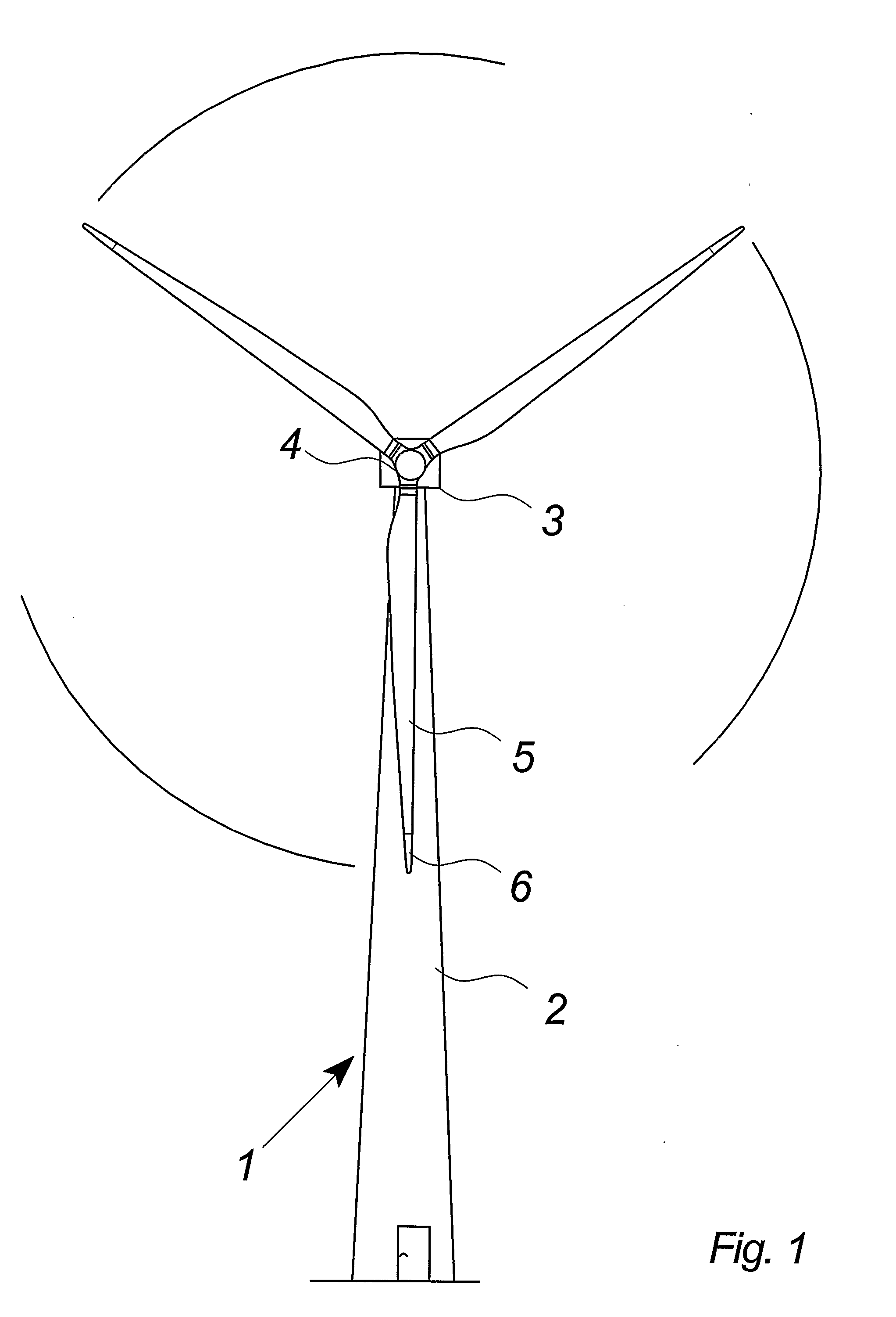
[0071]FIG. 1 illustrates a modern wind turbine 1 with a tower 2 and a wind turbine nacelle 3 positioned on top of the tower. The wind turbine rotor 5, comprising three wind turbine blades, is connected to the nacelle through the main shaft which extends out of the nacelle front.

[0072]As illustrated in the figure, wind beyond a certain level will activate the rotor due to the lift induced on the blades and allow it to rotate in a perpendicular direction to the wind. The rotation movement is converted to electric power, which is supplied to the utility grid.

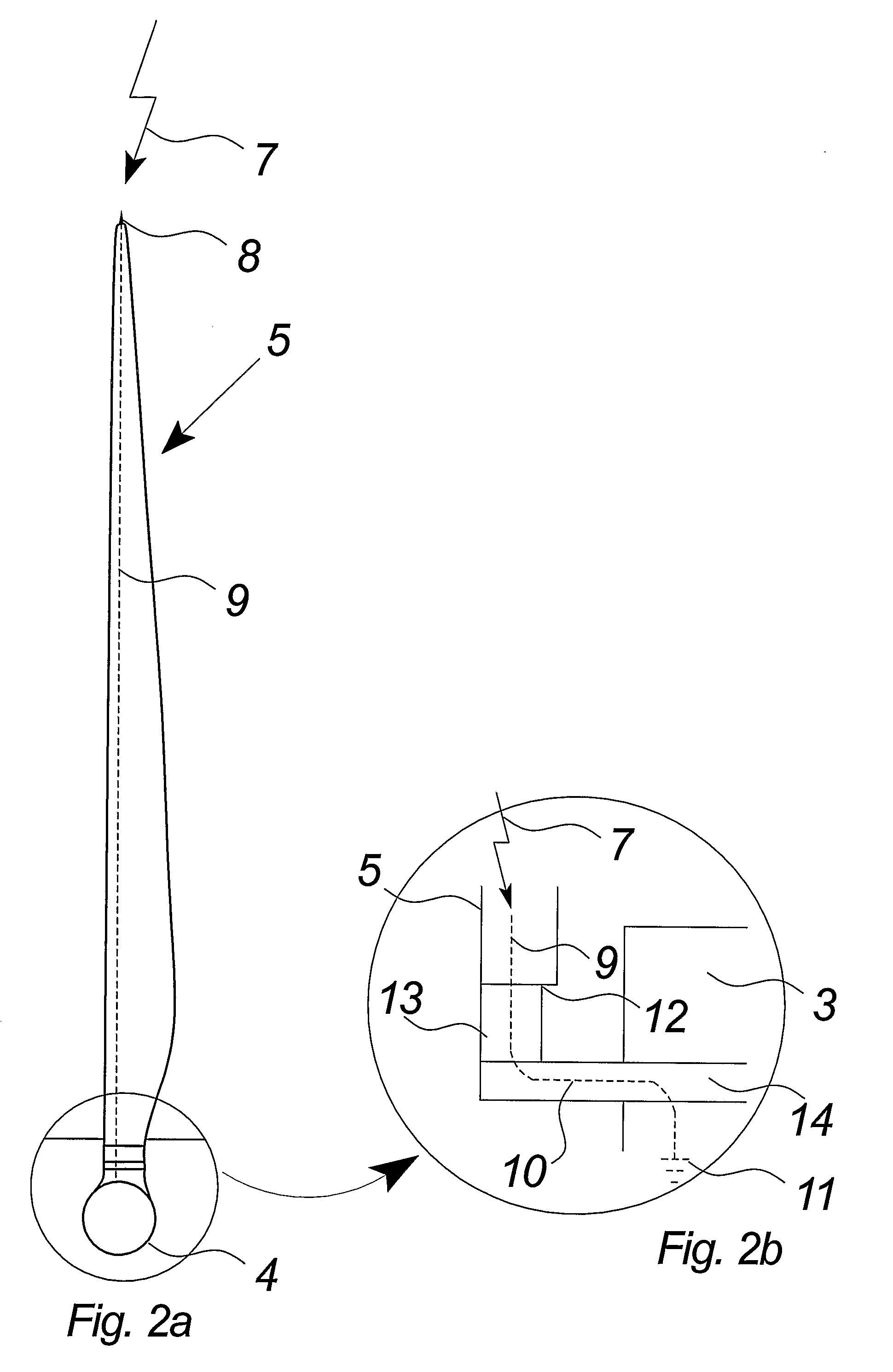
[0073]FIGS. 2a and 2b illustrate a normal wind turbine blade with a well-known lightning protection system. FIG. 2a illustrates a front view of the wind turbine blade seen and FIG. 2b a side view of the blade.

[0074]FIG. 2a illustrates how the tip 6 of the wind turbine blade 5 with a metal receptor 8 intercepts the lightning stroke 7. The receptor is connected to the lightning down conductor 9 inside the wind turbine blade 5. The co...


PUM


Abstract

The invention relates to a wind turbine (1) comprising stationary means such as a nacelle (3) and a tower (2) comprising stationary lightning protection means (46), and rotating means such as a rotor including at least one wind turbine blade (5) and shaft means (14), each of said at least one wind turbine blade (5) comprising rotating lightning protection means (47). The stationary and rotating lightning protection means (46, 47) comprise contact surfaces (17, 18) connected by lightning connection means (15). The lightning connection means (15) comprises at least two contact means (19, 19a, 19b) adapted for connecting said rotating and stationary lightning protection means (46, 47). Further, it comprises at least one electric conductor (30) establishing a dedicated connection between said at least two contact means (19, 19a, 19b) and force transferring means (26, 27) for said at least two contact means (19, 19a, 19b) establishing a continuous connection between said at least two contact means (19, 19a, 19b) and the contact surfaces (17, 18) of said stationary and rotating lightning protection means (46, 47). The invention also relates to lightning connection means (15) for a wind turbine (1), a method and use hereof.

Description

BACKGROUND OF THE INVENTION[0001]The invention relates to a wind turbine according to the preamble of claim 1, to lightning connection means according to the preamble of claim 12, method and use hereof.DESCRIPTION OF THE RELATED ART[0002]Typically, wind turbines are erected in areas with superior wind conditions such as rural areas comprising only a few tall obstacles e.g. trees or buildings. However, wind turbines are erected with increasingly higher towers and rotor blades in order to take the most efficient use of the wind and, with wind turbines being the tallest objects in an area, protection of the wind turbines against lightning strokes is thus a necessity.[0003]A well-known lightning protecting system for a wind turbine involves a lightning receptor at the tip of every rotor blade in order to capture the lightning stroke. The lightning is discharged to a ground potential via a down conductor inside the blade and down conductors in the nacelle and tower. In order to transfer ...

Claims


Application Information

Patent Timeline
Patent Type & Authority Applications(United States)
IPC IPC(8): H02G13/00F03D11/00
CPCF03D11/0033H02G13/00Y02E10/722Y10S415/908H02G13/80H02G13/40Y02E10/726F03D80/30Y02E10/72
Inventor MOLBECH, ALLAN LAURSEN
Owner VESTAS WIND SYST AS
Why Eureka
Try Eureka