Polarization microscope

US20090040601A1Inactive Publication Date: 2009-02-12OLYMPUS CORPORATIOJN

Image

  • Polarization microscope
  • Polarization microscope
  • Polarization microscope

Examples


first embodiment

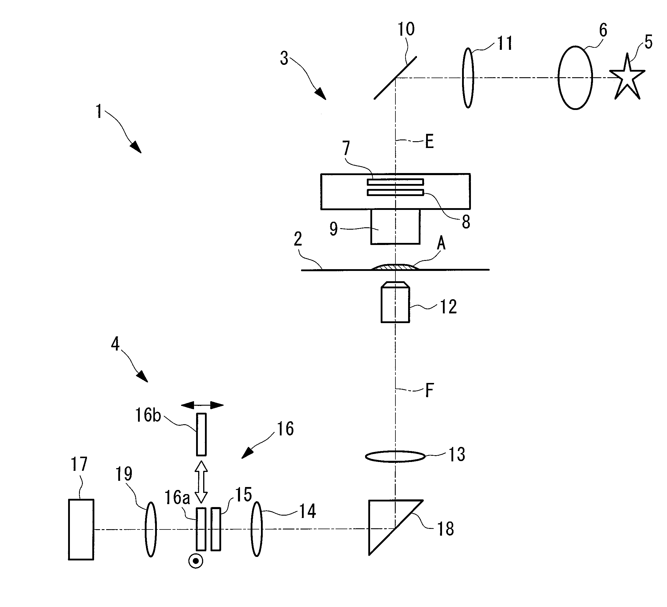
[0053]A polarization microscope 1 according to the present invention will be described below with reference to FIG. 1 and FIG. 2.

[0054]As shown in FIG. 1, the polarization microscope 1 according to this embodiment includes a stage 2 for mounting a specimen A, an illumination optical system 3 disposed above the stage 2, and an image-acquisition optical system 4 disposed below the stage 2.

[0055]The illumination optical system 3 includes a light source 5 for emitting illumination light E, a collector lens 6 for collecting the illumination light E from the light source 5, a polarizer 7 through which the collected illumination light E is passed to convert the polarization state thereof to linearly polarized light, an illumination-light retarder 8 through which is passed the illumination light E passing through the polarizer 7 to correct the polarization state thereof, and a condenser lens 9 for condensing the illumination light E passing through the illumination-light retarder 8 onto the...

second embodiment

[0081]Next, a polarization microscope 30 according to the present invention will be described below with reference to FIGS. 7 to 10.

[0082]In this embodiment, parts that are common to the configuration of the polarization microscope 1 according to the first embodiment described above are assigned the same reference numerals, and a description thereof is omitted here.

[0083]The polarization microscope 30 according to this embodiment, in which the numerical aperture of the illumination light E radiating the specimen A is made sufficiently small, does not include the illumination-light retarder 8 in an illumination optical system 31, as shown in FIG. 7. Another difference is that the prism 18 and the absorption filter 21, which have reflecting surfaces that deteriorate the polarization state before correction by an observation-light retarder 32, are not provided. Reference numeral 33 in the drawing is an excitation filter for extracting excitation light E from light from a light source 3...


PUM


Abstract

It in an object to acquire a high-precision polarization image. Provided is a polarization microscope comprising an illumination optical system 3 including a light source, a polarizer for converting a polarization state of illumination light from the light source, and a condenser lens for condensing the illumination light transmitted through the polarizer onto a specimen; an image-acquisition optical system including an objective lens for collecting observation light from the specimen, an analyzer for converting a polarization state of the observation light collected by the objective lens, and an image-acquisition device for acquiring the observation light transmitted through the analyzer; an observation-light angle correcting element for correcting changes in rotation angle of a polarization plane of the observation light in the image-acquisition optical system; and an observation-light phase-difference correcting element for correcting changes in phase difference between P-polarization and S-polarization of the observation light in the image-acquisition optical system, wherein amounts of correction of these correcting elements vary in directions intersecting an optical axis.

Description

TECHNICAL FIELD[0001]The present invention relates to a polarization microscope.BACKGROUND ART[0002]In a known polarization microscope in the related art, polarized light, to which a predetermined polarization state is applied by transmitting light emitted from a light source through a polarizer, is radiated onto a specimen, and of the reflected light or transmitted light from the specimen, only the light that is transmitted through an analyzer is acquired (for example, see Patent Document 1). The polarizer and analyzer are generally aligned so that their transmission directions are orthogonal (crossed-Nicol alignment).[0003]In such a polarization microscope, when no specimen is disposed, theoretically, none of the light can pass through the analyzer, and the viewing field becomes black. Then, when a specimen is disposed, due to differences in birefringence and orientation at each part of the specimen, light having different polarization states is transmitted through the analyzer an...

Claims


Application Information

Patent Timeline
12 Feb 2009
Publication
US20090040601A1
IPC
G02B21/06
CPC
G02B21/14; G02B21/0092
Inventors
SAITO, YOSHIHARU; TAKATSUKA, HIROFUMI