
Vehicle control apparatus and method

a technology for vehicle control and control apparatus, which is applied in mechanical devices, transportation and packaging, instruments, etc., can solve the problems of uncomfortable feeling of the occupants of the vehicle, and achieve the effects of increasing product durability, reducing impact, and increasing production cos

Inactive Publication Date: 2009-02-12
TOYOTA JIDOSHA KK
View PDF0 Cites 46 Cited by
  • Summary
  • Abstract
  • Description
  • Claims
  • Application Information

AI Technical Summary

Benefits of technology

The invention provides a vehicle control apparatus and method that reduces the impact on the drive power input portion when the parking-lock device is unlocked, which prevents uncomfortable feelings for the occupants of the vehicle and increases the durability of the product. This is achieved by detecting the operation state of the brake device and the gradient of the road on which the vehicle is located, and controlling the rotational torque generation portion to generate rotational torque in the direction corresponding to the detected gradient of the road. This eliminates the need for increasing the product durability and prevents discomfort for the occupants of the vehicle.

Problems solved by technology

Such rocking of the vehicle may cause uncomfortable feeling of the occupants of the vehicle.

Method used


Image

  • Vehicle control apparatus and method
  • Vehicle control apparatus and method
  • Vehicle control apparatus and method

Examples


Embodiment Construction

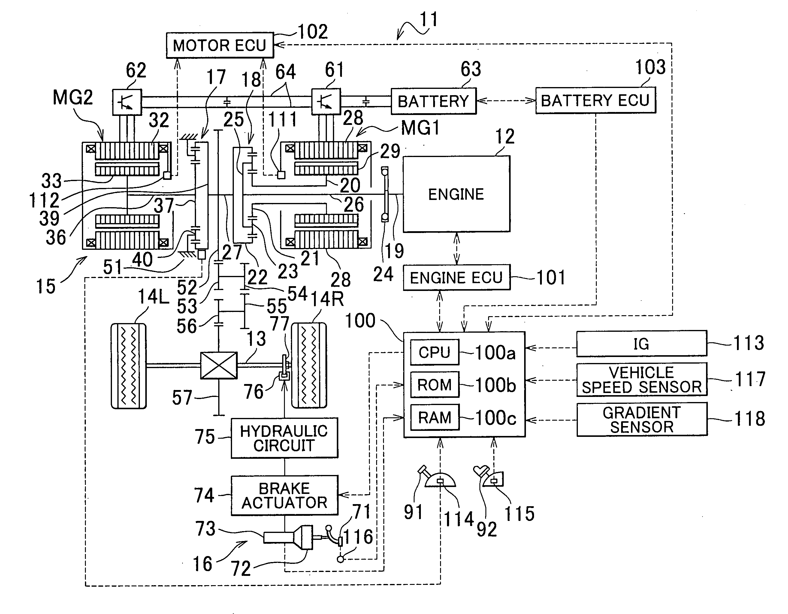
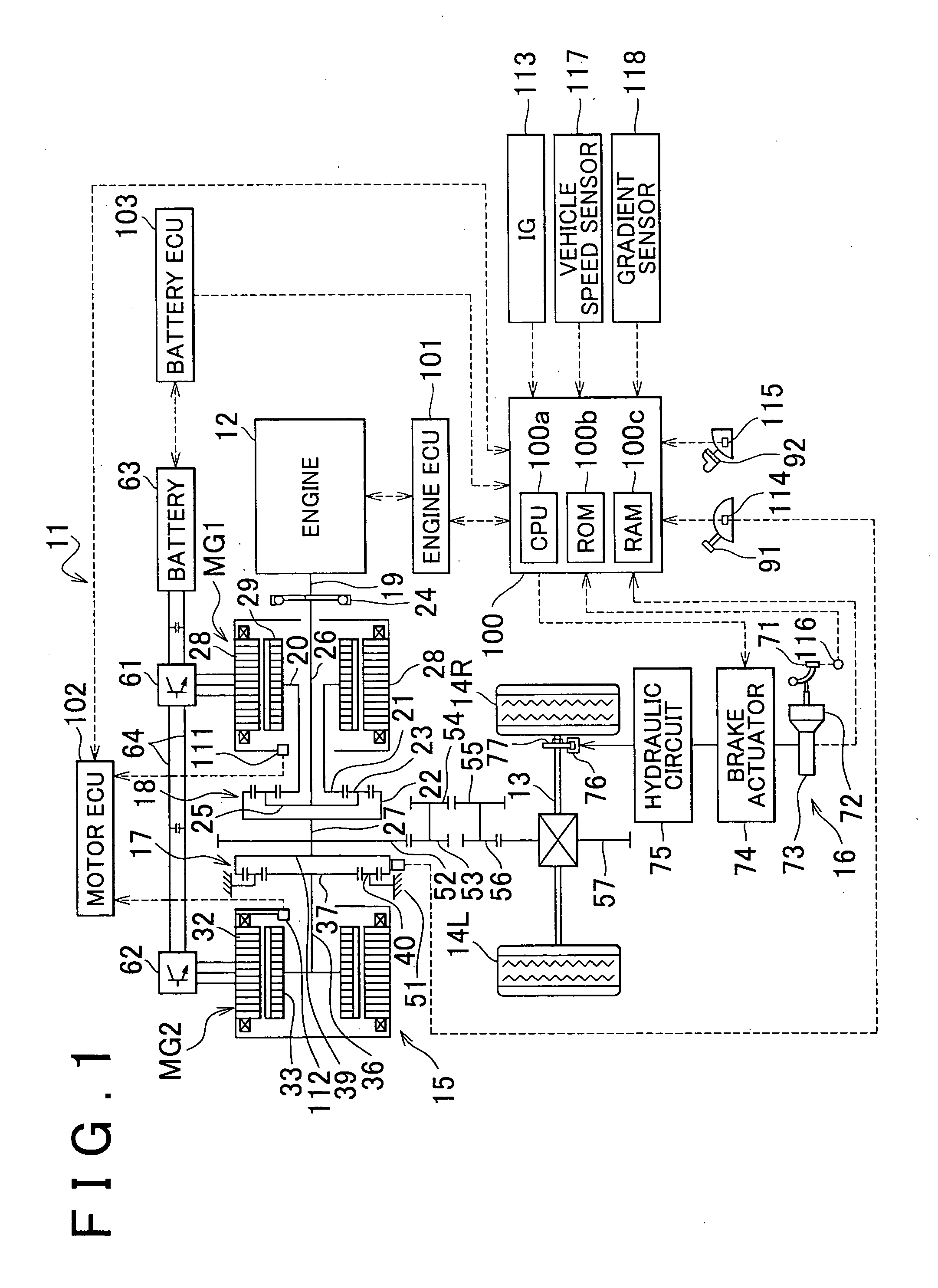
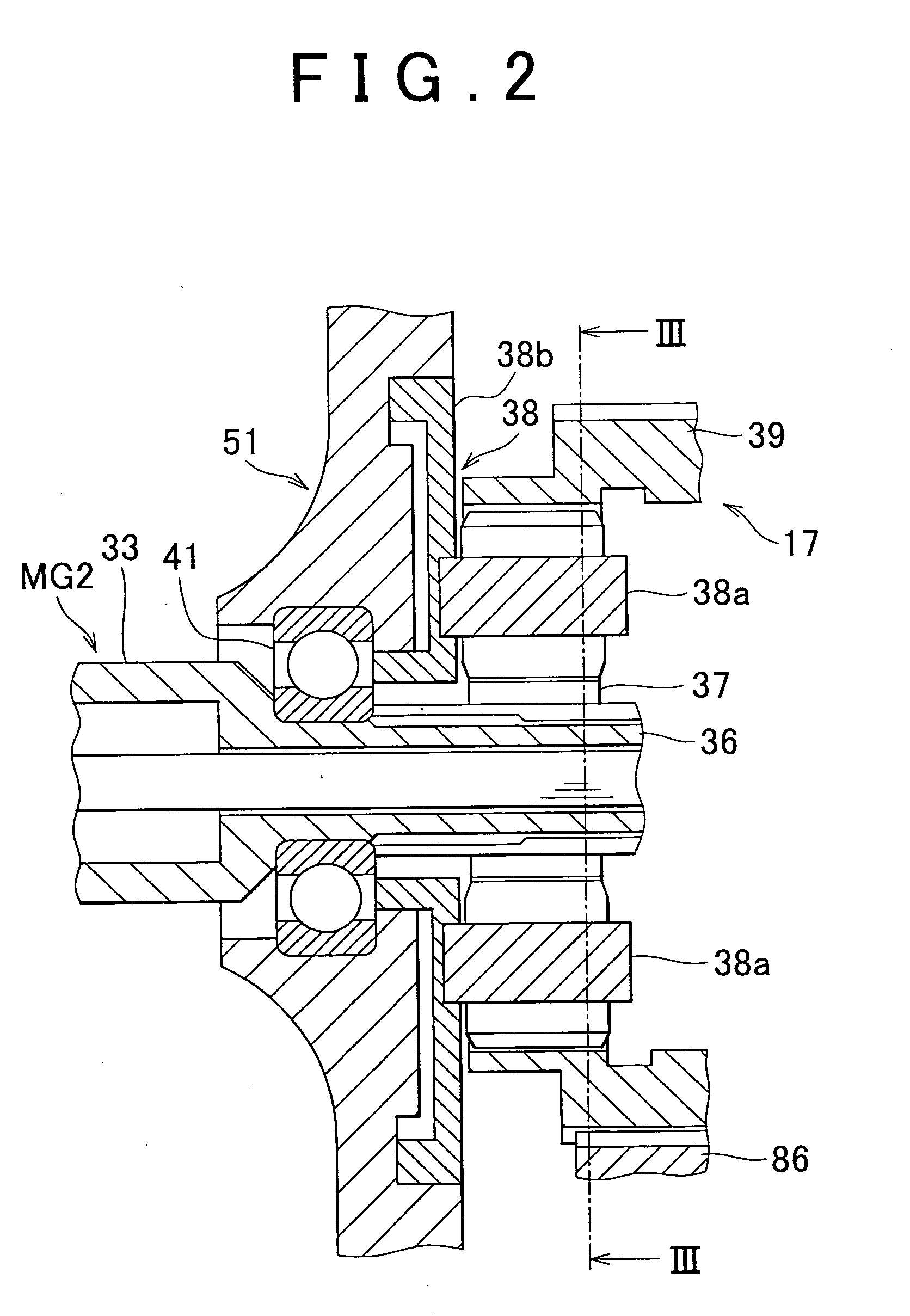
[0045]Hereinafter, vehicle control apparatuses according to example embodiments of the invention will be described with reference to the drawings. FIG. 1 to FIG. 6 are views illustrating a vehicle control apparatus according to an example embodiment of the invention. This vehicle control apparatus is incorporated in a hybrid vehicle.

[0046]First, the configuration of the vehicle control apparatus will be described. Referring to FIG. 1, a hybrid vehicle 11 has an engine 12 that is an internal combustion engine, a drive power distribution apparatus 15 that transmits the drive power of the engine 12 to drive wheels 14L, 14R via a driveshaft 13, a brake system 16 that applies braking force to the drive wheels 14L, 14R, and a hybrid vehicle electronic control unit 100 (will be referred to as “hybrid vehicle ECU”) that controls the overall operation of the hybrid vehicle 11.

[0047]The drive power distribution apparatus 15 has a motor generator MG1, a motor generator MG2, a reduction gear un...


PUM


Abstract

In a case where, in order to stop a hybrid vehicle on a hill, a brake device is turned on and then the shift lever is shifted to the parking position (“P” position) to lock a parking-lock device and then the brake device is turned off and then the brake device is turned on despite that torsional torque is acting on the drive shaft, a motor generator, which is an inertial object having a large weight, is driven to rotate in a rotational direction corresponding to the direction of gradient of the road, so that the resultant rotational torque is transmitted to a sun gear, to pinions, and to a ring gear.

Description

INCORPORATION BY REFERENCE[0001]The disclosure of Japanese Patent Application No. 2007-208970 filed on Aug. 10, 2007 including the specification, drawings and abstract is incorporated herein by reference in its entirety.BACKGROUND OF THE INVENTION[0002]1. Field of the Invention[0003]The invention relates to vehicle control apparatuses and vehicle control methods and more particularly relates to vehicle control apparatuses and vehicle control methods for vehicles having a parking-lock device that is operated between a lock position where it locks the drive wheels of the vehicle not to rotate and an unlock position where it allows the drive wheels to rotate.[0004]2. Description of the Related Art[0005]In vehicles having a drive power transmission mechanism incorporating gears meshed so as to transmit drive power of an internal combustion engine to the drive wheels of the vehicle via gears, typically, a mechanical parking-lock device is provided which locks the drive wheels by meshing ...

Claims


Application Information

Patent Timeline
Patent Type & Authority Applications(United States)
IPC IPC(8): F16H63/34B60K6/36B60K6/40B60K6/405B60K6/445B60W10/10B60W20/00
CPCB60K6/40B60K6/445B60L2240/30B60L2240/642B60W10/08B60W10/18Y02T10/6239B60W2510/186B60W2550/142F16H63/483Y02T10/7291Y02T90/16B60W30/18118B60W2552/15Y02T10/62Y02T10/72
Inventor TOMITA, MAKOTO
Owner TOYOTA JIDOSHA KK
Learn More