
Complex multifuntional relay system and control method therefor

a multi-functional, relay technology, applied in the direction of computer control, program control, instruments, etc., can solve the problems of improving efficiency and limiting efficiency, and achieve the effects of improving product durability, improving product functionality, and providing differentiated performan

Active Publication Date: 2020-07-30
ACMEX ALMAZ CO LTD
View PDF0 Cites 0 Cited by
  • Summary
  • Abstract
  • Description
  • Claims
  • Application Information

AI Technical Summary

Benefits of technology

The complex multifunctional relay system and control method described in this patent allow for the use of both digital and analog circuits to perform various functions. The system uses a microprocessor to continuously compare numerical values with real-time detection, allowing for the prevention of malfunctioning of the motor and other circuit parts. The system also performs various functions such as inductive load operation and motor starting overcurrent blocking, improving product durability and responsiveness in various industrial fields. Overall, this patent aims to provide a more efficient, complex, and responsive relay system that improves product functionality and performance.

Problems solved by technology

In recent years, some devices having a simple combination type of circuit including an earth leakage circuit breaker, an arc circuit breaker and the like have been developed, but since this is merely a simple combination of related two functions, there is a limitation in improving efficiency.

Method used


Image

  • Complex multifuntional relay system and control method therefor
  • Complex multifuntional relay system and control method therefor

Examples


Embodiment Construction

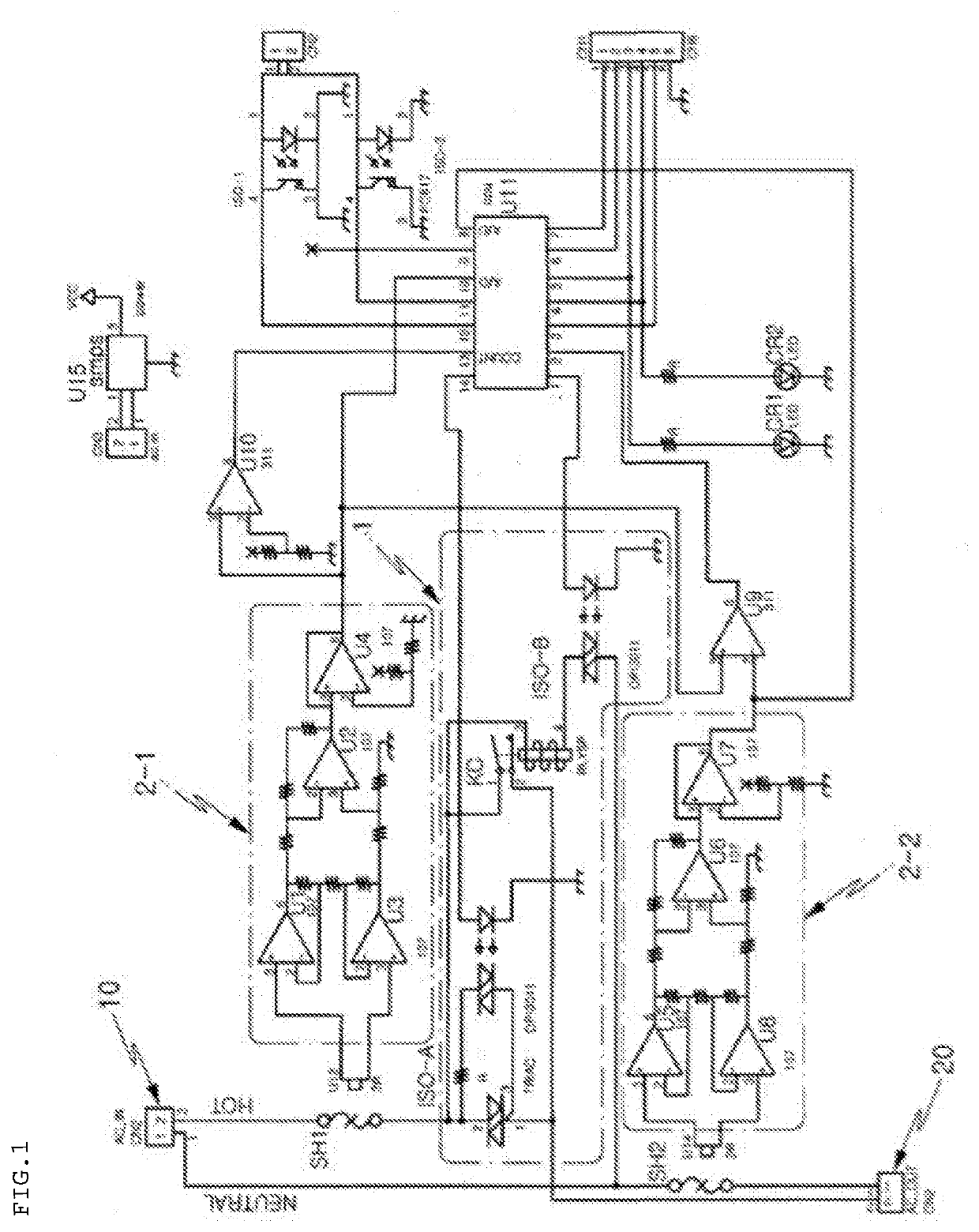
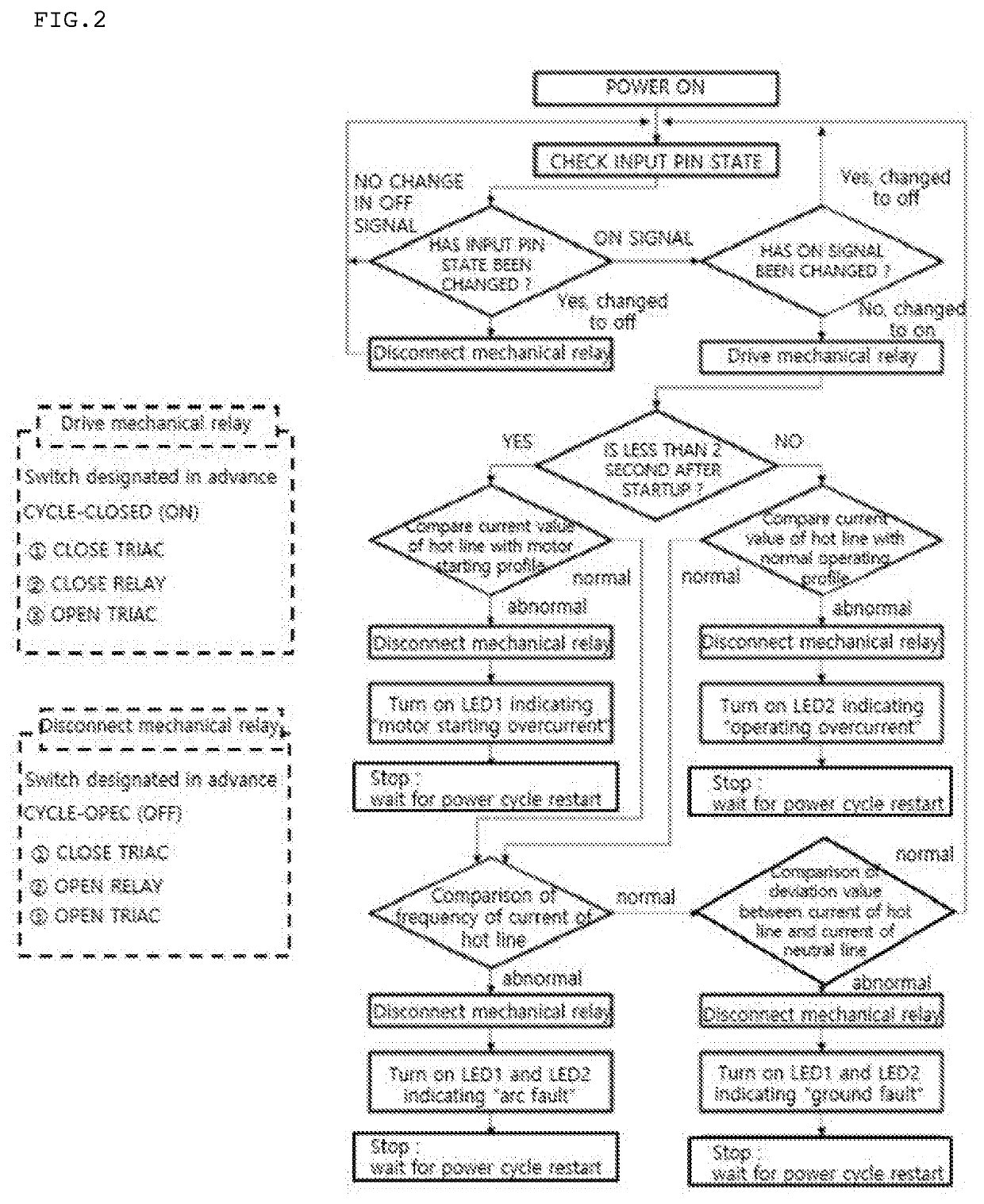
[0018]A complex multifunctional relay system and a control method therefor of the present disclosure will be divided into the system and the control method and will be described in more detail by the circuit configuration diagram of FIG. 1 and the flowchart of FIG. 2.

[0019]First, as illustrated in FIG. 1, the complex multifunctional relay system of the present disclosure includes a power control means 1, which is connected to a hot line HOT and a neutral line NEUTRAL of an AC circuit that receives AC power through an input terminal 10 and supplies the AC power to a load 20 such as a motor, a pump, or various industrial machines and is connected in parallel to the hot line, insulation differential amplifiers 2-1 and 2-2 circuit-connected to the hot line HOT and the neutral line NEUTRAL through current shunts SH1 and SH2, and a microprocessor U11 connected to the power control means 1 and the insulation differential amplifiers 2-1 and 2-2 to perform monitoring and control the power su...


PUM


Abstract

Provided are a complex multifunctional relay system capable of complexly performing an overcurrent blocking function, an arc blocking function, and an earth leakage blocking function by a relay circuit, and a control method therefor. The complex multifunctional relay system includes an AC circuit including a hot line and a neutral line, a power control means connected in parallel to the hot line, insulation differential amplifiers circuit-connected to the hot line and the neutral line through current shunts, a microprocessor connected to the power control means and the insulation differential amplifiers to perform monitoring and control the power supply of the power control means, a first comparator connected to the current shunt and the insulation differential amplifier and connected to the microprocessor so as to check ground fault, and a second comparator connected between the current shunt / the insulation differential amplifier and the microprocessor so as to check arc fault.

Description

TECHNICAL FIELD[0001]The present disclosure relates to a complex multifunctional relay system which allows various functions to be complexly performed at the same time by a relay circuit in which analog circuits and digital circuits are mixed when power is transmitted to a load such as a motor via a relay, and a control method therefor.BACKGROUND ART[0002]In general, when AC power is supplied from a power input terminal to a load such as a motor, a relay is used when control of a circuit operation is required in an electric circuit, and various control functions are individually performed by a relay circuit or a separate electric circuit.[0003]According to the following Patent Documents, technologies for an earth leakage circuit breaker, an overcurrent circuit breaker, and an arc circuit breaker have been disclosed as control functions on an electric circuit, but all these control functions have been made individually to perform respective functions.[0004]In recent years, some devic...

Claims


Application Information

Patent Timeline
Patent Type & Authority Applications(United States)
IPC IPC(8): H02H3/16H02H1/00H02H3/10G05B19/042
CPCH02H1/0015G05B19/042H02H3/10H02H3/162H02H1/0007H02H1/0038H02H3/021H02H3/04H02H3/08H02H3/32H02H3/34H02H3/46H02H7/08
Inventor AN, SUN-TAEMASTEN, JR., JAMES WILLIAM
Owner ACMEX ALMAZ CO LTD
Learn More