
Sound dampening assembly for automotive exhaust system

a technology for automotive exhaust and sound dampening, which is applied in the direction of machines/engines, electrical apparatus casings/cabinets/drawers, transportation and packaging, etc. it can solve the problems of limited space in the vehicle and in the engine compartment in particular, additional or unexpected noises in the exhaust system, and packaging concerns, so as to reduce the overall structure borne, dampen exhaust gas pulsation, and reduce the noise content of pipe radiated and tail pip

Inactive Publication Date: 2007-07-24
GM GLOBAL TECH OPERATIONS LLC
View PDF4 Cites 15 Cited by
  • Summary
  • Abstract
  • Description
  • Claims
  • Application Information

AI Technical Summary

Benefits of technology

The assembly effectively reduces structure-borne, pipe radiated, and tail pipe noise by targeting specific frequencies earlier in the exhaust system, providing targeted noise performance and flexible design, even in space-constrained environments.

Problems solved by technology

Often, however, additional or unexpected noises occur in the exhaust system.
Moreover, packaging concerns remain an issue in the design of the exhaust system because these traditional tuning elements consume a relatively large amount of space in the vehicle, which space in the vehicle and in the engine compartment in particular is limited.

Method used


Image

  • Sound dampening assembly for automotive exhaust system
  • Sound dampening assembly for automotive exhaust system
  • Sound dampening assembly for automotive exhaust system

Examples


Embodiment Construction

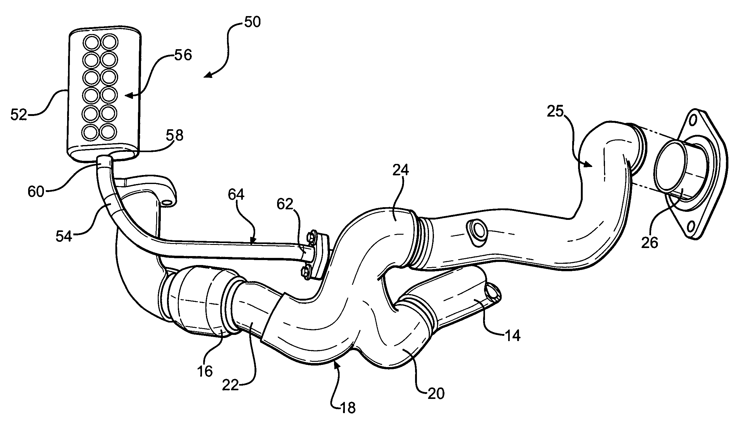
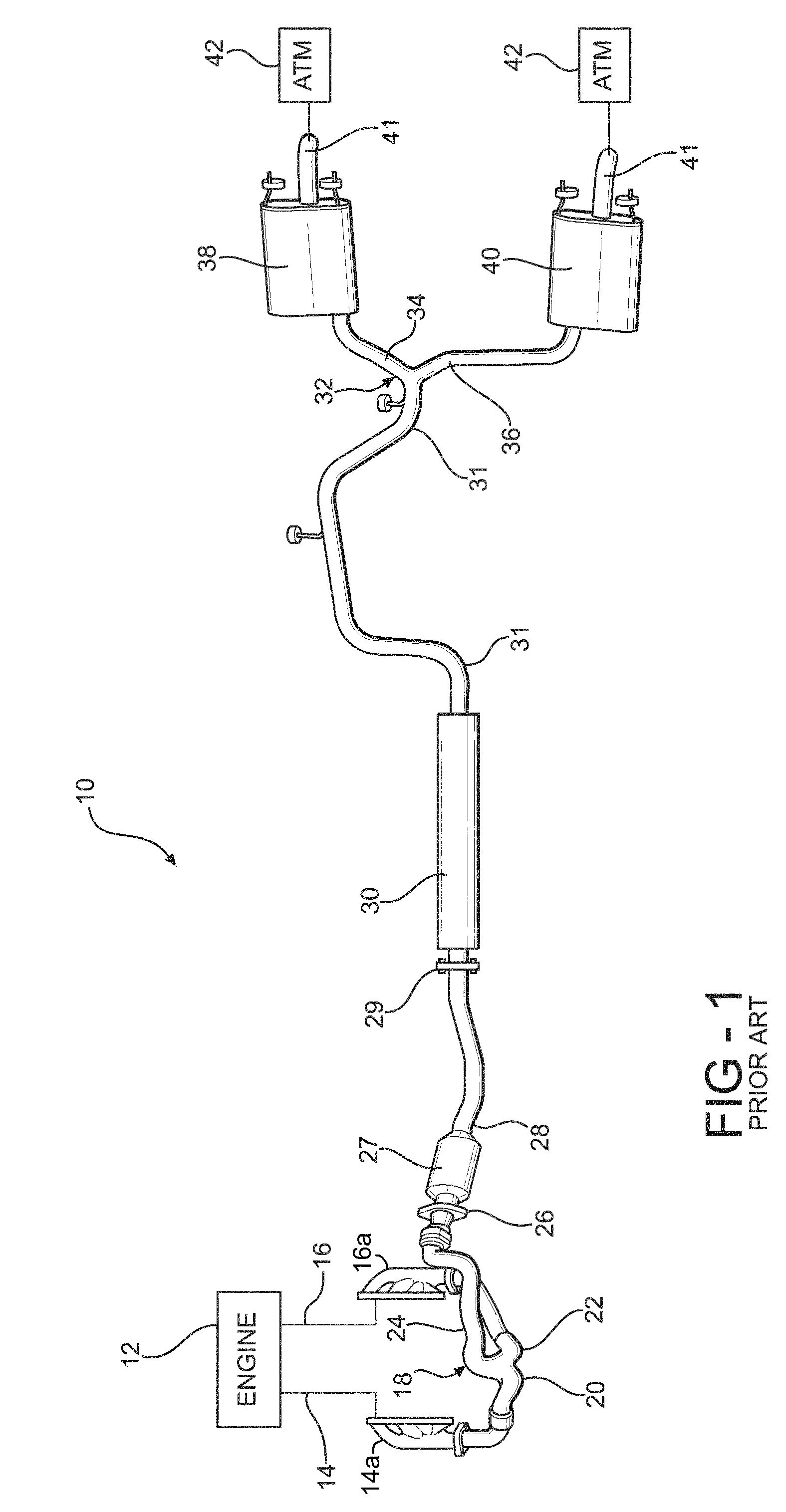
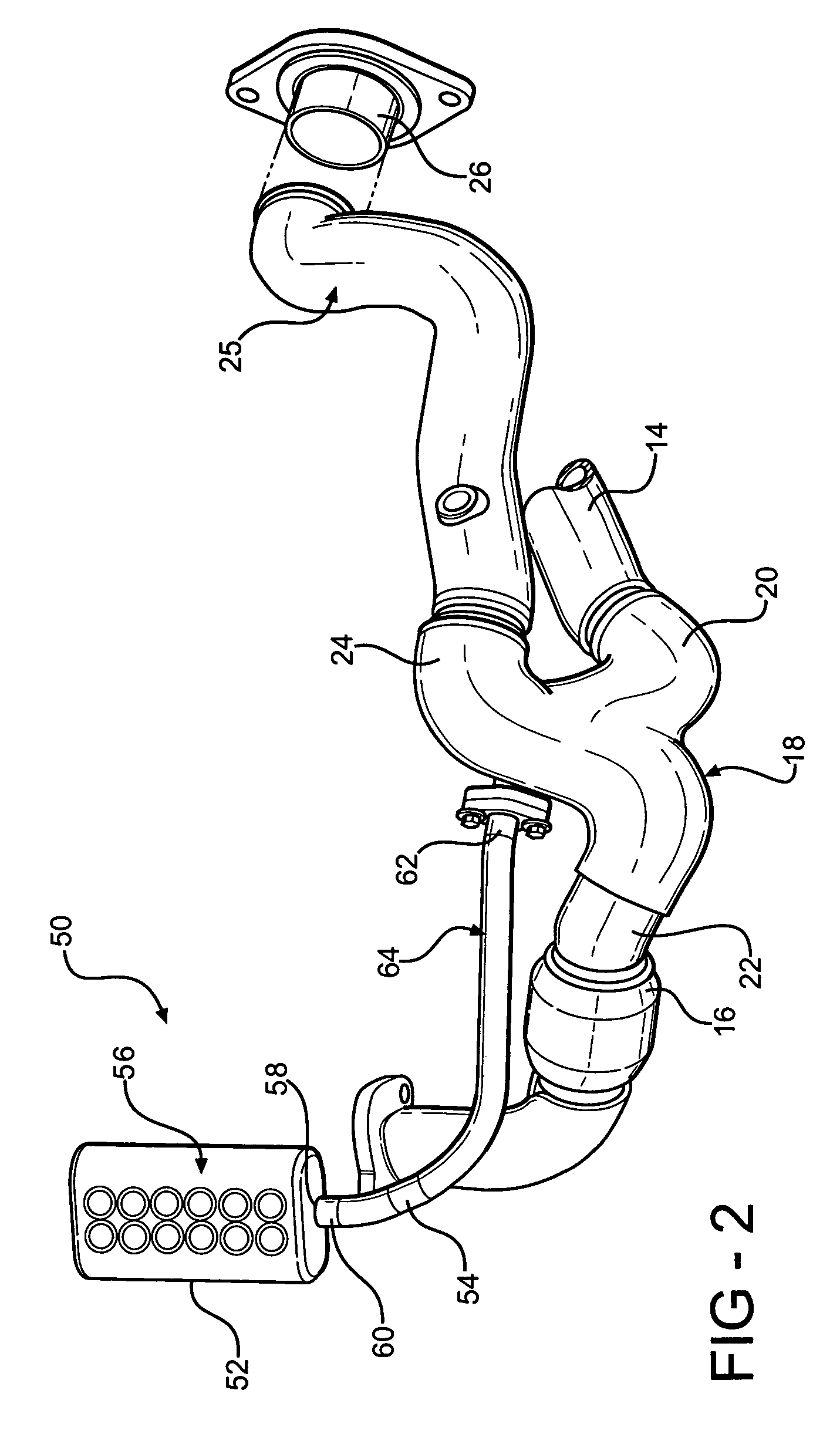
[0014]Referring now to FIG. 1, a prior art exhaust system is indicated generally at 10. The exhaust system 10 is adapted to receive an exhaust gas stream from an engine, such as an internal combustion engine, indicated schematically at 12. A first outlet 14 and a second outlet 16 of the engine 12 are in fluid communication with a Y-pipe 18. The outlets 14 and 16 of the engine 12 may receive exhaust flow, for example, from two separate banks of cylinders (not shown) from the engine 12—in which case, the outlets 14 and 16 are constituted in part by a first exhaust manifold 14a and a second exhaust manifold 16a. respectively. The Y-pipe 18 includes a pair of inlets 20 and 22 for connection with the respective outlets 14 and 16 of the engine 12 and a single outlet 24. The outlet 24 of the Y-pipe 18 is in fluid communication with an inlet 26 of a catalytic converter assembly 27. An outlet 28 of the catalytic converter assembly is in fluid communication with an inlet 29 of the resonator 3...


PUM


Abstract

A sound dampening assembly adapted to engage an exhaust pipe in an automotive engine exhaust system adjacent an outlet of an internal combustion engine. The assembly includes a bottle portion having a single opening and an interior defining a predetermined amount of volume and a neck portion having a first end attached to the opening of the bottle portion and extending from the bottle portion. The neck portion is in fluid communication with the bottle portion interior and includes a second end adapted to be attached to the exhaust pipe. The neck portion has an interior defining a predetermined amount of volume and the bottle portion and the neck portion are sized to attenuate vibration at a predetermined frequency in the exhaust system.

Description

BACKGROUND OF THE INVENTION[0001]The present invention relates generally to automotive exhaust systems and, in particular, to a sound dampening assembly for an automotive exhaust system.[0002]Automotive exhaust systems include piping and other components that treat an exhaust gas stream as well as rout the stream from an inlet connected to an internal combustion engine to an outlet to atmosphere.[0003]Mufflers are disposed in the exhaust systems and are intended to smooth the exhaust gas pulsations and make the noise emitting from the tail pipe as inaudible as possible. To dampen and smooth the exhaust gas pulsations, mufflers and / or resonators use a combination of reflection and absorption techniques typically employing such traditional elements as helmholtz resonators, pipes perforated with holes and venturi nozzles. These traditional elements are sized and dimensioned (i.e. tuned) to have specified natural frequencies. These tuning elements, then, will dampen the frequencies of i...

Claims


Application Information

Patent Timeline
Patent Type & Authority Patents(United States)
IPC IPC(8): H05K5/00
CPCF01N1/02F01N13/011F01N13/009F01N2530/04
Inventor OSTERKAMP, DALE F.KURZAWA, ANDREW J
Owner GM GLOBAL TECH OPERATIONS LLC
Learn More