
System for maximizing server utilization in a resource constrained environment

a server and resource-constrained technology, applied in the field of data processing systems, can solve the problems of insufficient power and cooling available for operating all blade servers, inconvenient use of available hardware resources, and limited power consumption, so as to reduce the computing power reduce the power consumption of the blade server, and increase the steady-state utilization

Inactive Publication Date: 2009-02-12
INT BUSINESS MASCH CORP
View PDF26 Cites 85 Cited by
  • Summary
  • Abstract
  • Description
  • Claims
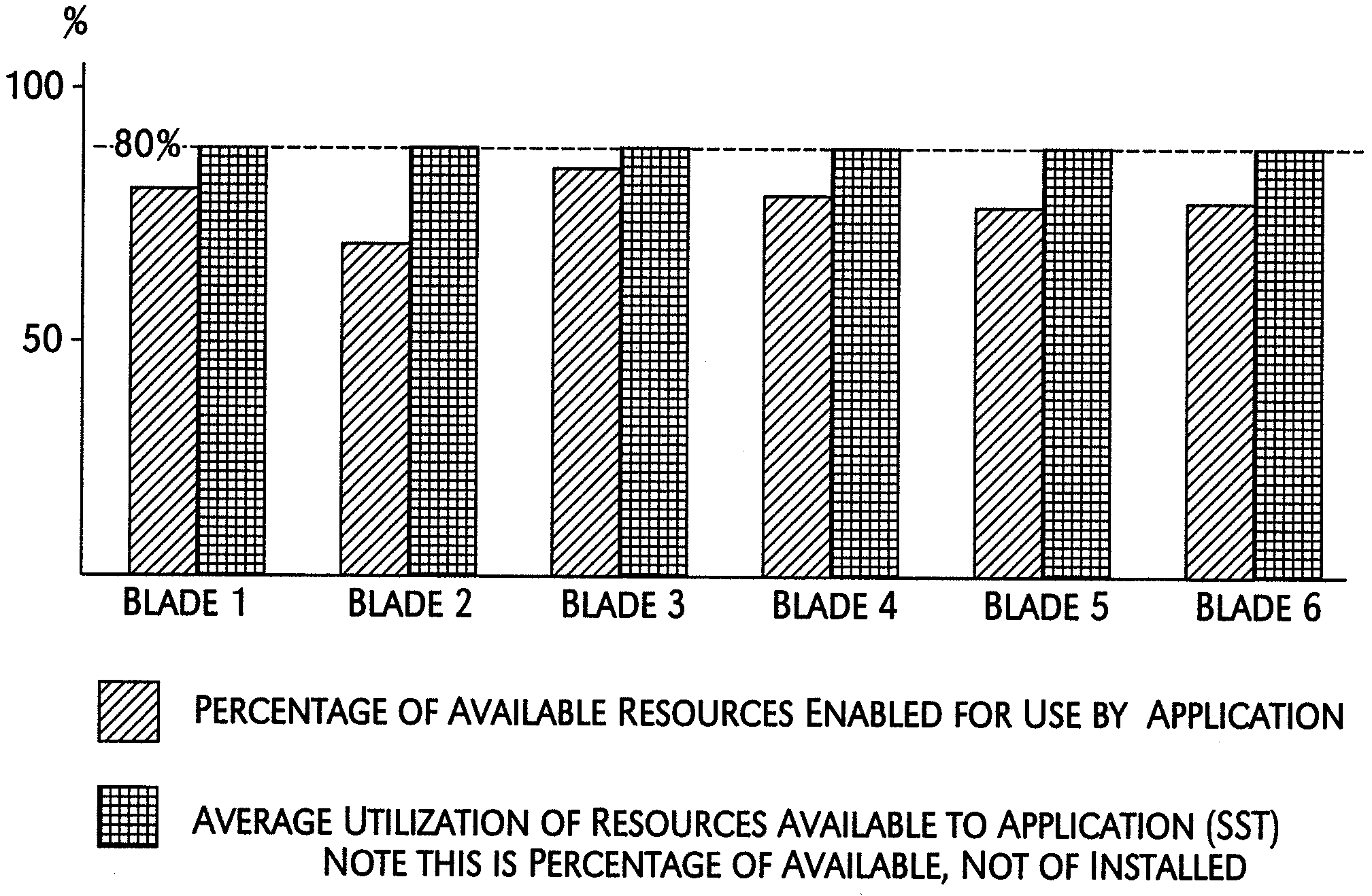
  • Application Information

AI Technical Summary

Benefits of technology

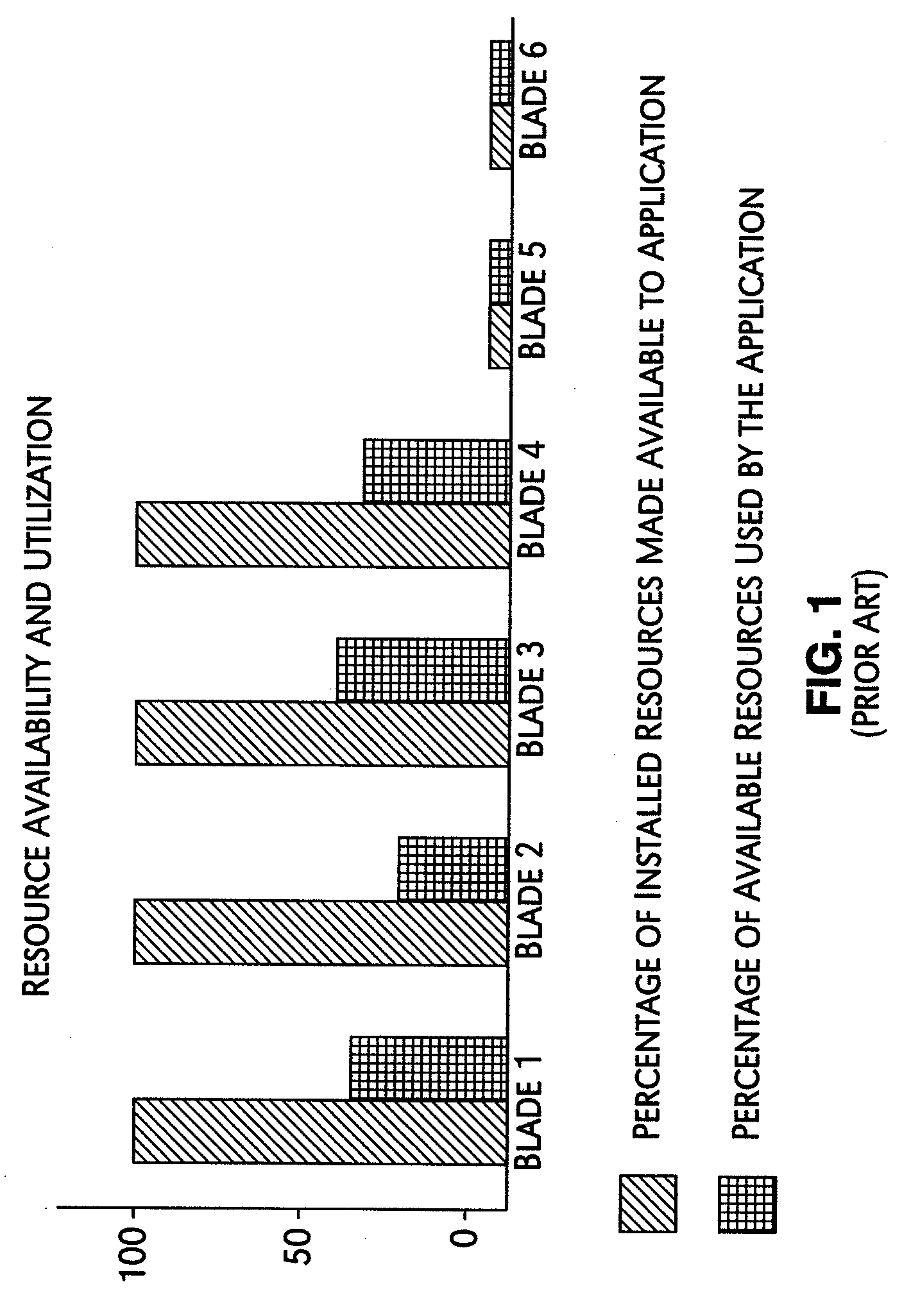
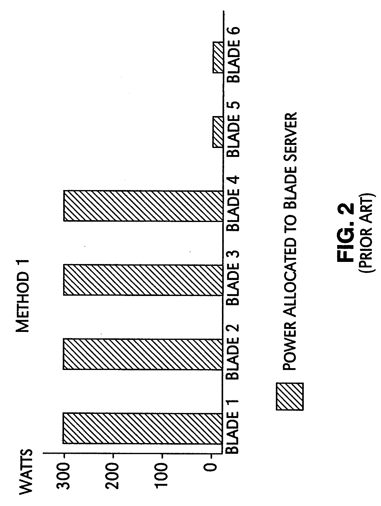
[0010]The present invention addresses the foregoing needs by providing a mechanism for controlling the hardware resources on a blade server, and thereby limiting the power consumption of the blade server in an enforceable manner. The hardware resources that are controlled include the base frequency of the central processing unit (CPU) as well as power to individual banks of physical memory, for example dual-inline memory modules (DIMMs). The hardware resources are controlled to constrain the power required by the blade server, thereby reducing computing power of the blade server. The system and method of the present invention tunes the hardware resources in dependence on actual server utilization such that applications running on the blade server only have the allocated hardware resources available to them. Deactivated hardware resources are powered off and are so withheld from the operating system when they are not required. In this manner, power consumption in the entire chassis can be managed such that all blade servers can be powered on and operate at higher steady-state utilization. While there may be insufficient power and cooling available for operating all blade servers at 100% hardware resources, sufficient computing power may be achieved by operating all blade servers at some lower percentage of enabled hardware resources. Thus, the present invention provides a method for brokering allocated power among the blade servers in a blade center chassis and thereby distributing the available electrical power more effectively among a greater number of powered on blade servers. The utilization of the powered on resources in a blade center is also improved with the present invention.
[0011]One component of the present invention comprises hardware resource monitoring by a monitoring agent software running in the operating system that can monitor and report the utilization of physical memory and CPU cycles. The present invention leverages off standard protocols and interface support for throttling CPU speeds and hot plugging memory modules. A chassis power management software, running on a management module, serves as the resource broker within the blade center and may scale down the resources available to an application on a blade server to achieve some steady state threshold (SST), for example 90%. This has the effect of placing a limit on that server's power consumption, which is less than the value associated with the server running at full capacity. The chassis power management software may then allocate less power to the blade server than would be required for full-power operation. Through a shrewd combination of throttling the CPU and disabling memory DIMMs, the upper limit on power consumption is enforced. Even if the demands on the hardware resources from the application rise sharply or spike suddenly, the available hardware resources and power consumption remain constrained. When a monitoring agent software running on the blade server detects that utilization of a server resource is exceeding the SST and climbing towards a trending upwards threshold (TUT), a determination according to algorithm or policy will be made regarding the amount of additional blade server resources (CPU cycles or DIMMs) to make available to the operating system. The additional physical resources on the individual blade server will have a corresponding requirement for shared resources in the blade center chassis, i.e., electrical power and cooling capacity. The resource monitoring agent software will request that the management module, acting in the capacity of a resource broker for the common pool of unused power and cooling resources in the chassis, allocate sufficient power from the pool to the blade server for adjusting upwards the amount of server resources available to the application. Similarly, when the resource monitoring agent software detects that monitored values for server resources have fallen below a trending downwards threshold (TDT), it can remove resources from the operating system and power them down. The monitoring agent on the blade server then sends a notification to the management module that the blade server is thereby releasing its corresponding allocation of the shared resources back to the pool. For the purposes of controlling power consumed by the CPU, simple CPU utilization may represent values for the monitored threshold quantities SSU, TUT, and TDT, in one embodiment of the present invention. For the purposes of controlling power consumed by memory in another example of the present invention, percent of physical memory used, number of page faults, or a combination thereof may represent values for the monitored threshold quantities SSU, TUT, and TDT.
[0012]The present invention provides numerous advantagous benefits for manageability issues. The present invention allows the continued allocation to individual applications of a single server for ensuring that resources are available for meeting peak requirements during usage of the application. When an application is running below peak requirements, power consumption by individual servers is reduced by scaling down resources in use. When the aggregate total of resources required to support servers running at maximum utilization exceeds that which is available to them in the common pool, the present invention allows the servers to execute at levels tailored to their steady state requirements while ensuring that utilization spikes do not cause the resources available in the common pool to be exceeded.
[0014]Another object of the present invention is to increase the effective utilization of blade servers in a blade center chassis for a given computing workload at a given power consumption level.
[0016]Another object of the present invention is to provide for a common pool of reserve power that may be allocated to individual blade servers so that they may operate at power consumption levels tailored to their steady state requirements.
[0017]Still another object of the present invention is ensuring that utilization spikes do not cause reserve power resources in the common pool to be exceeded and preventing thereby a total loss of power in the blade center chassis, caused by overloading the common power supply or by exposure to excessive thermal loading.

Problems solved by technology

While there may be insufficient power and cooling available for operating all blade servers at 100% hardware resources, sufficient computing power may be achieved by operating all blade servers at some lower percentage of enabled hardware resources.
Even if the demands on the hardware resources from the application rise sharply or spike suddenly, the available hardware resources and power consumption remain constrained.

Method used


Image

  • System for maximizing server utilization in a resource constrained environment
  • System for maximizing server utilization in a resource constrained environment
  • System for maximizing server utilization in a resource constrained environment

Examples


Embodiment Construction

[0032]In the following description, numerous specific details are set forth such as specific word or byte lengths, etc. to provide a thorough understanding of the present invention. However, it will be obvious to those skilled in the art that the present invention may be practiced without such specific details. In other instances, well-known circuits have been shown in block diagram form in order not to obscure the present invention in unnecessary detail. For the most part, details concerning timing considerations and the like have been omitted inasmuch as such details are not necessary to obtain a complete understanding of the present invention and are within the skills of persons of ordinary skill in the relevant art.

[0033]Refer now to the drawings wherein depicted elements are not necessarily shown to scale and wherein like or similar elements are designated by the same reference numeral through the several views.

[0034]One prior art method for allocating power within a blade cent...


PUM


Abstract

A mechanism for controlling the hardware resources on a blade server, and thereby limiting the power consumption of the blade server is disclosed. The enforceable hardware resources that are controlled include the base frequency of the central processing unit (CPU) as well as power to individual banks of physical memory, for example dual-inline memory modules (DIMMs). The hardware resources are tuned in dependence on actual server utilization such that applications running on the blade only have the allocated hardware resources available to them. Deactivated hardware resources are powered off and are so ‘hidden’ from the operating system when they are not required. In this manner, power consumption in the entire chassis can be managed such that all server blades can be powered on and operate at higher steady-state utilization. The utilization of the powered on resources in a blade center is also improved.

Description

TECHNICAL FIELD[0001]The present invention relates in general to data processing systems, and in particular, to communications network devices referred to as blade servers.BACKGROUND INFORMATION[0002]The use of servers as devices within communications networks is well known in the art. A server is equipment that makes available file, database, printing, facsimile, communications or other services to client terminals / stations with access to the network the server serves. When the server permits client / terminal station access to external communications network it is sometimes known as a gateway. Servers are available in different sizes, shapes and varieties. Servers may be distributed throughout a network or they may be concentrated in centralized data centers.[0003]Advances in centralized data processing centers have resulted in smaller form factors for server devices and an increase in the density of processing units, thereby reducing space requirements for computing infrastructure....

Claims


Application Information

Patent Timeline
Patent Type & Authority Applications(United States)
IPC IPC(8): G06F1/28
CPCG06F1/206G06F1/263Y02B60/1275H05K7/20836G06F1/28Y02D10/00
Inventor MERKIN, AARON E.
Owner INT BUSINESS MASCH CORP
Learn More