Multiple configuration cylinder valve spring

a technology of valve spring and configuration, which is applied in the field of multi-configuration cylinder valve spring, can solve the problems of oil leakage, damage to the technician, and gradual loss of the valve stem seal

Inactive Publication Date: 2009-02-19
DUARTE ROMEO ANTONIO
View PDF7 Cites 15 Cited by
  • Summary
  • Abstract
  • Description
  • Claims
  • Application Information

AI Technical Summary

Benefits of technology

[0007]It is an object of the present invention to provide an effective way to compress the valve spring and remove its locks of an internal combustion engine for the purpose of replacing valve stem seals or the valve spring itself.
[0009]It is another object of the preferred embodiment of the present invention to insured the less amount of time use to performed the task of the removal and installation of valve springs.
[0012]Furthermore, in accordance with another preferred embodiment of the present invention all parts are rigid, made of steel or a suitable material, this makes the tool durable and safer.
[0013]Furthermore, in accordance with another preferred embodiment of the present invention the cylindrical body element of the multiple configuration valve spring compressor can move back and forward, and left to right when mounted on the transversal bar that is slidably dispose on the bracket for the purpose of clearing obstacles and allow the positioning of the tool over any valve.
[0016]Furthermore, it is another object of the present invention, the pushrod slides up and down in the cylindrical body of the spring compressor and is returned to the rest position by a spring, the push rod is made to provide a push action and for attachment of the compressing member and also help to adjust the high of the compressing member.

Problems solved by technology

within the time, valve stem seal lose effectiveness gradually and oil leaks into the combustion chambers, this oil get burned during the power stroke producing hydrocarbon that exit from the tail pipe.
The cylinder is pressurized with air in order to hold the valves, the disadvantage was the set up of the tool that permits the valve spring compressor to move from one valve spring to the other, it is also a time consuming method, and another disadvantage here was or still a problem of firmly holding the tools in place that sometimes led to injuries to the technician.
The disadvantage is that this tool only fits in few type cylinder head design.

Method used


Image

  • Multiple configuration cylinder valve spring
  • Multiple configuration cylinder valve spring
  • Multiple configuration cylinder valve spring

Examples


Embodiment Construction

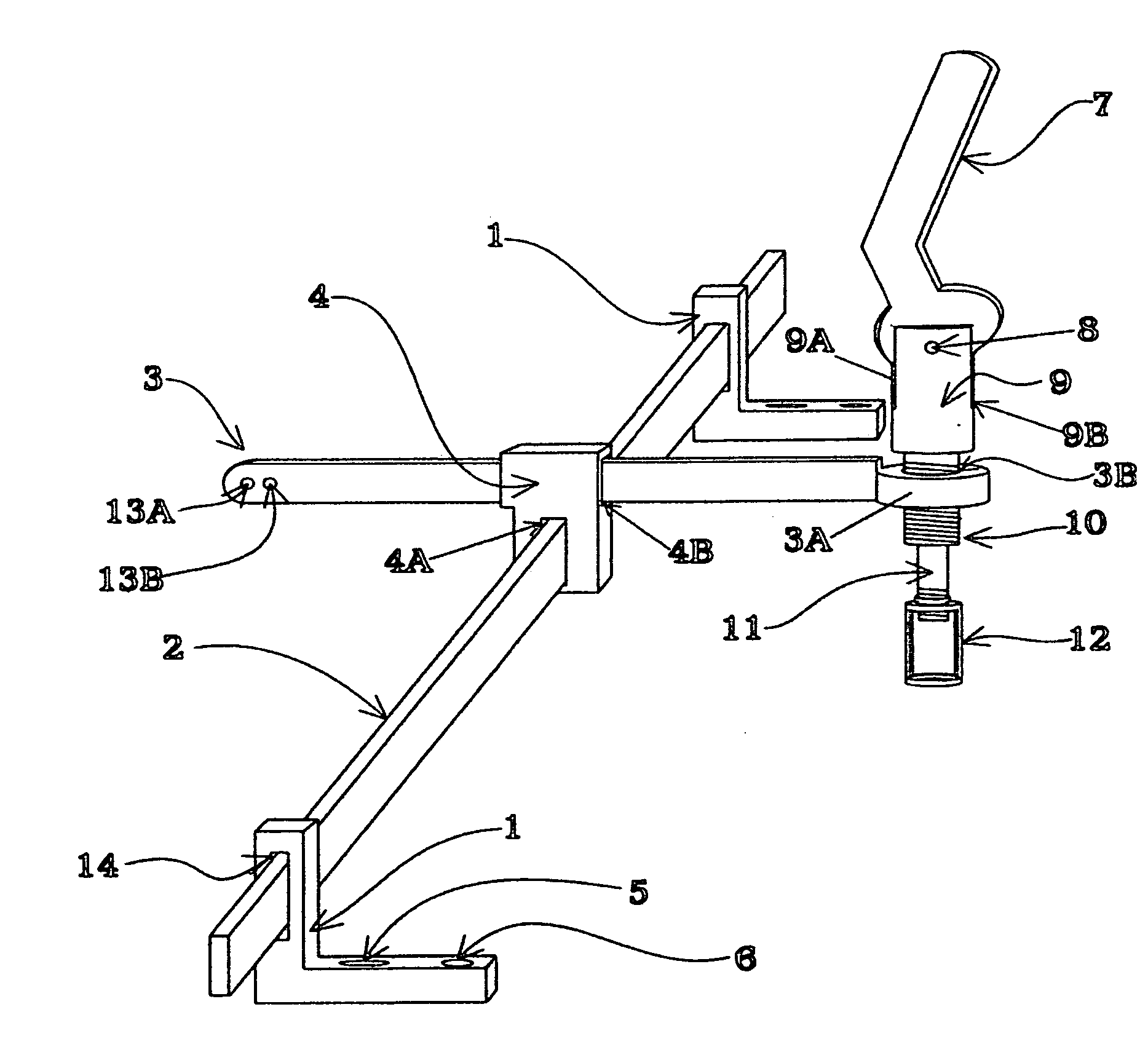
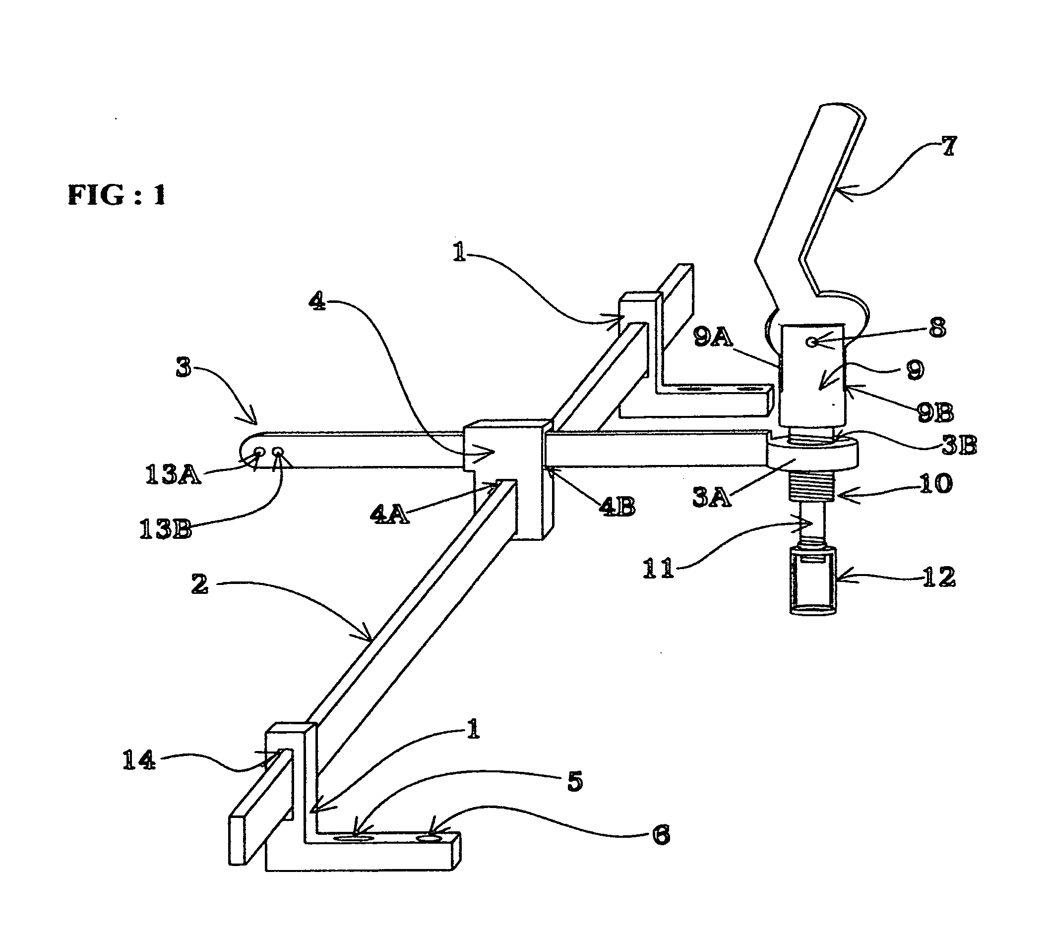
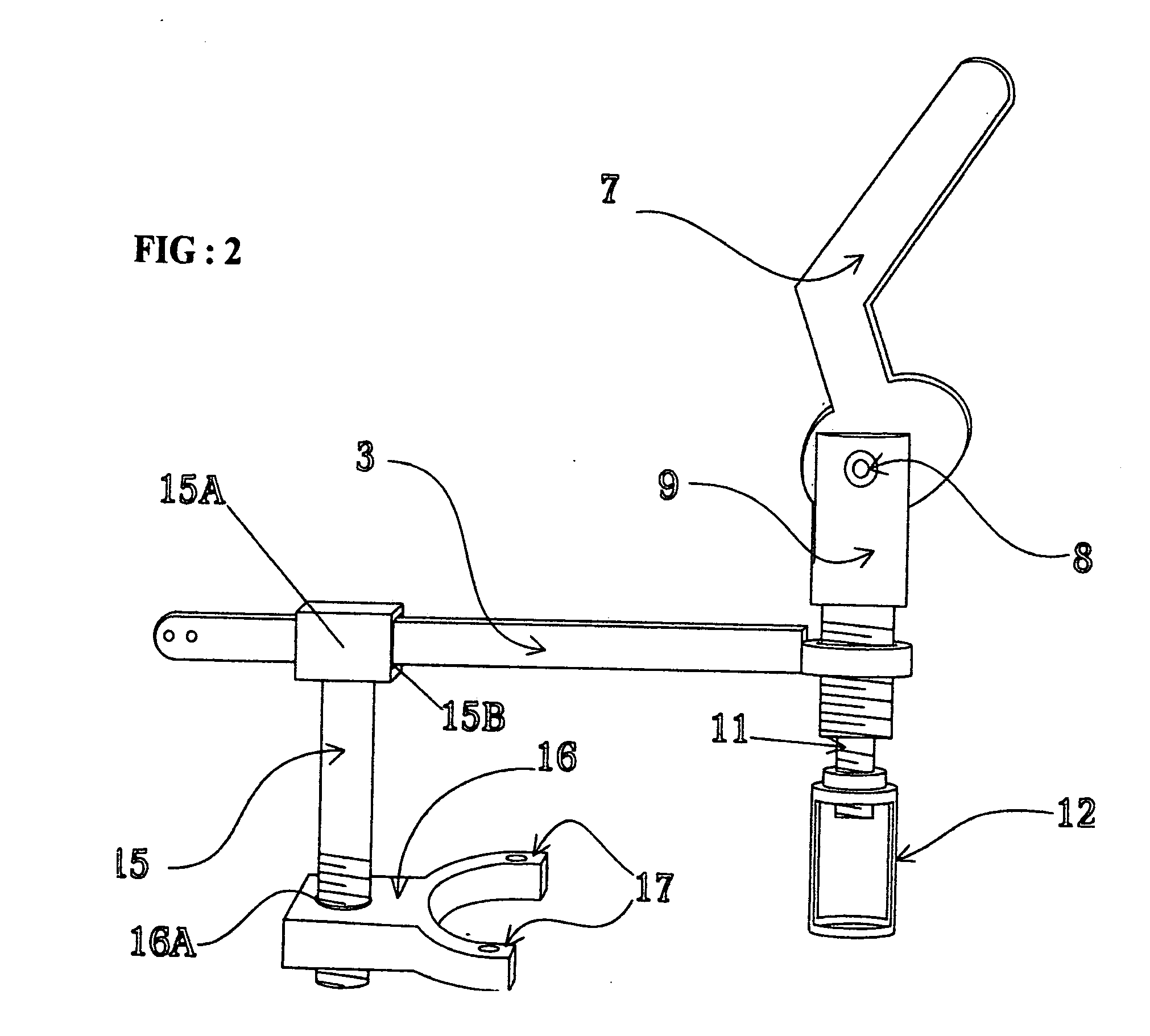
[0028]Due to the necessity of replacing valve stem seals or the spring of the cylinder valves on an internal combustion engine, it is required to create a special service tool that allow technician to overcome the major difficulties when performing this task. In the past technicians are being injured when performing this operation due to the lack of reliable tools, also time consuming procedures of very limited benefits for the owner of the motor vehicle and technicians.

[0029]The most important part of all; is the reduction of harmful contaminants to the atmosphere and our environment that are the cause of many respiratory diseases specially for senior citizens and young kids, good reasons for all States of our country to enforces the law about inspection maintenance test required by every State in order to reduce the amount of harmful pollutants exiting from the tail pipe of every automobile. Vehicles that do not pass the inspection maintenance test and safety inspection are not al...


PUM

PropertyMeasurementUnit
ninety degree angleaaaaaaaaaa
angleaaaaaaaaaa
angleaaaaaaaaaa

Abstract

Special service tool and method for compressing cylinder valve springs for the removal and installation of their locks or keepers and for replacement of valve stem seals or brocken springs on an internal combustion engine, while the head still mounted on the engine or is on a work bench. Service tool comprising a multiple of attachment members for configuring the tool as need depending of the cylinder head design. Support means temporarily secured over the cylinder head and employing existing threaded opening for securing camshaft caps are arrange to mount the tool over slidably dispose bars and brackets, this method allow technicians to overcome the problems of removal and replacement of overhead valve springs by performing this task faster and in a safer manner.

Description

[0001]This non-provisional application claims the benefits of prior provisional application No. 60 / 964,840 filed on Aug. 15, 2007FIELD OF THE INVENTION[0002]The present invention relates generally to special service tools and more specifically to tools use in the service or repair of internal combustion engines. the special tool allow technician to easy overcome the problems of removal and replacement of valve springs on overhead camshaft cylinder head as need for the replacement of valve stem seals or the spring itself. Service tool having a multiple of attachment members.BACKGROUND OF THE INVENTION[0003]within the time, valve stem seal lose effectiveness gradually and oil leaks into the combustion chambers, this oil get burned during the power stroke producing hydrocarbon that exit from the tail pipe. Each valve is located on the cylinder head and is held firmly against it seat by a spring that presses it against the valve seat and the spring retainer and is secured to the valve s...

Claims


Application Information

Patent Timeline
Patent Type & Authority Applications(United States)
IPC IPC(8): B23P19/04B23P17/00
CPCB25B27/24B25B27/26Y10T29/53561Y10T29/49314Y10T29/53843Y10T29/53961
Inventor DUARTE, ROMEO ANTONIO
Owner DUARTE ROMEO ANTONIO
Why Eureka
Try Eureka