Method for manufacturing an edge protector and die assemblies therefor

a technology of die assembly and edge protector, which is applied in the direction of engine components, mechanical equipment, metal-working equipment, etc., can solve the problems of insufficient fabrication of edge protectors having three dimensional configurations, damage to blades, and prone to chipping or cracking

Active Publication Date: 2009-02-19
HONDA MOTOR CO LTD
View PDF11 Cites 23 Cited by
  • Summary
  • Abstract
  • Description
  • Claims
  • Application Information

AI Technical Summary

Benefits of technology

[0015]According to the present invention, in the primary press forming process, the blank sheet metal is draw worked so as to form the curved bent portion a that conforms to the leading edge of the blade while the planar portions b and c are given with a substantially straight configuration so that the a preformed work piece Wb having an approximately U-shaped cross section may be produced. In the secondary press forming process, the planar portions b and c of the preformed work piece are stretch formed into a final shape that conforms to the corresponding profile of the

Problems solved by technology

A blade made of such composite material has a higher mechanical strength and toughness than other more conventional metallic materials for the given weight, but is known to be more prone to chipping or cracking.
In particular, when an aircraft is on the ground, sands and gravels that could be ingested into the engine may be impinged upon the leading edges of the blades of the stator fan, and this could cause damages to the blades.
Therefore, conventional press forming processes for fabricating edge protectors of two dimensional configurations have become inadequate for fabricating edge protectors having three dimensional configurations.
However, these processes have some problems.
The el

Method used


Image

  • Method for manufacturing an edge protector and die assemblies therefor
  • Method for manufacturing an edge protector and die assemblies therefor
  • Method for manufacturing an edge protector and die assemblies therefor

Examples


Embodiment Construction

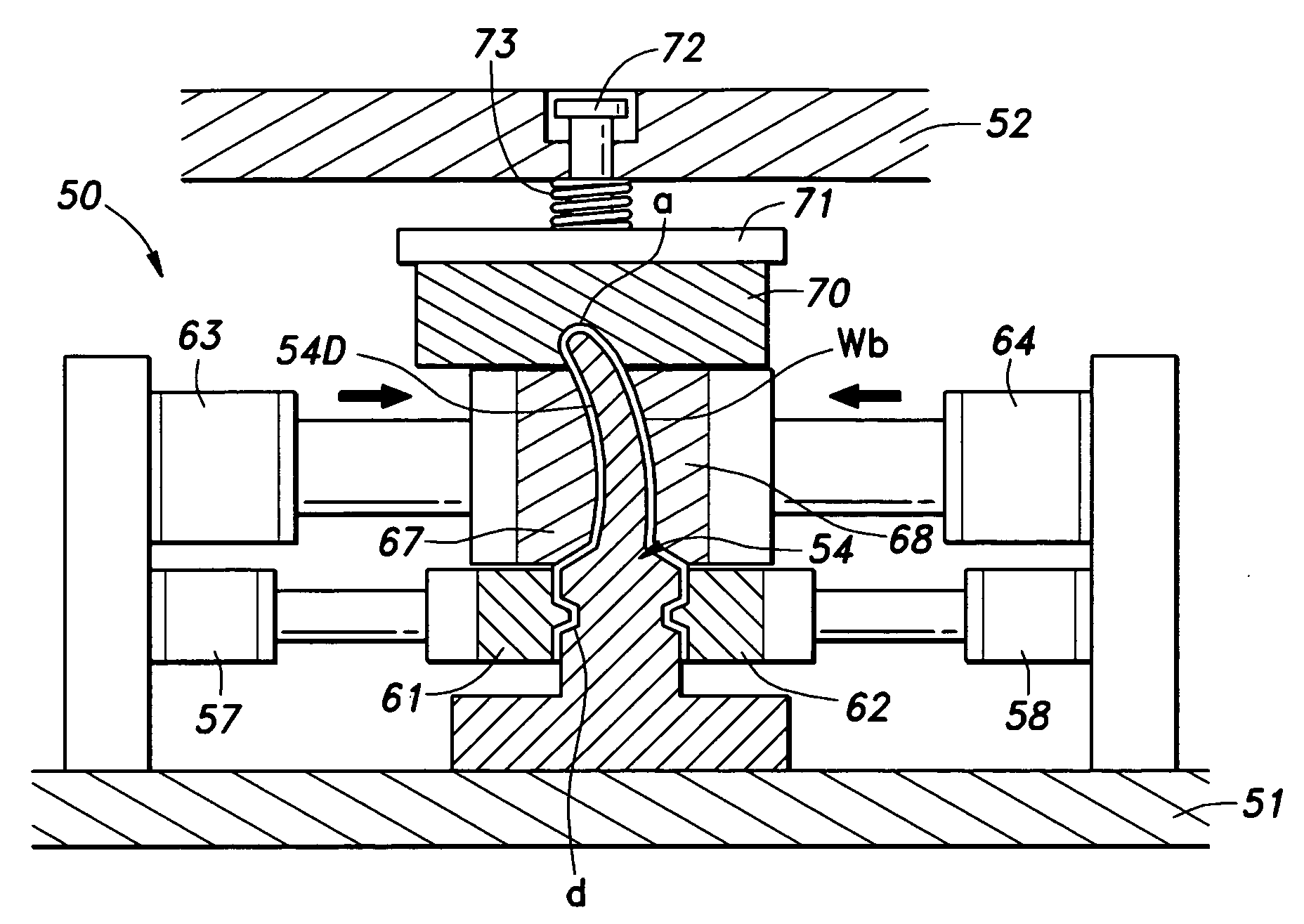
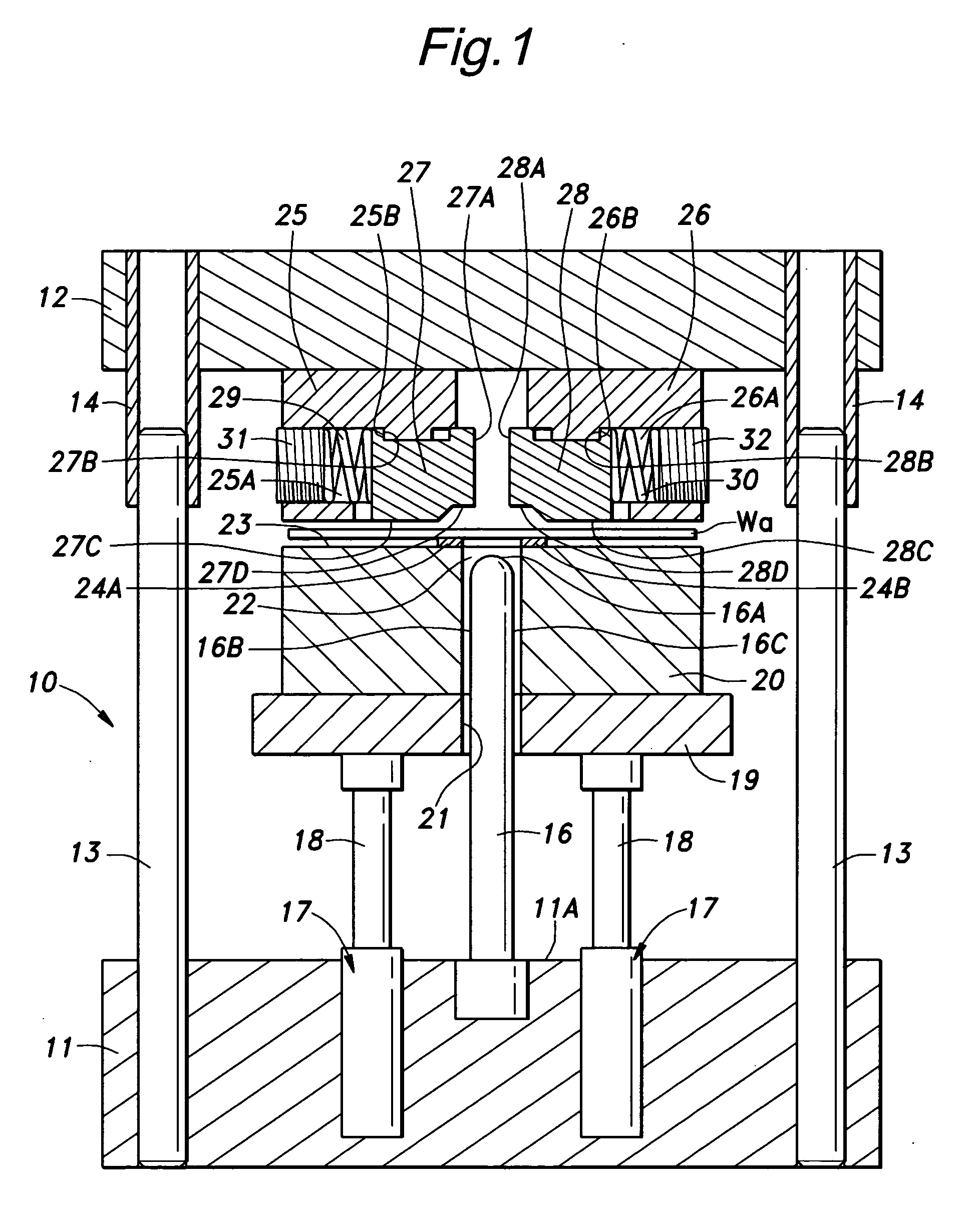
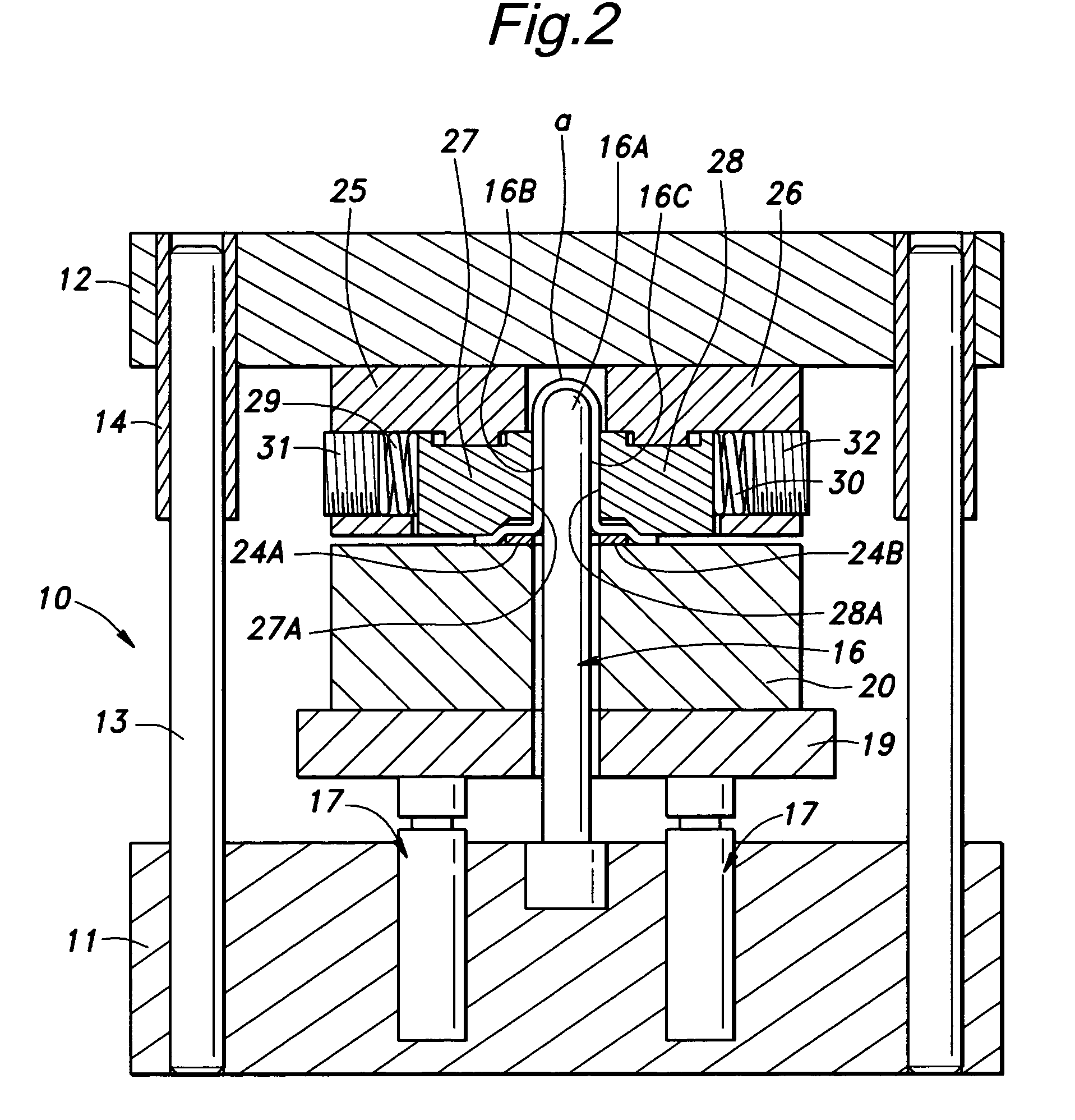
[0024]A method for manufacturing an edge protector and die assemblies for performing such a method embodying the present invention are described in the following with reference to FIGS. 1 to 6. As illustrated in FIG. 7, the edge protector 100 that is desired to be manufactured is made of a stainless steel sheet having a thickness t of about 0.1 mm, a total length L of about 30 to 300 mm, and a width W of about 5 to 30 mm, and is given with a U-shaped cross section that includes a bent portion a and a pair of planar portions b and c. The bent portion a is given with a three dimensional inner contour that closely fits the outer contour of the leading edge of a blade (aerofoil) which is desired to protected, and the planar portions b and c are also slightly curved so as to conform to the corresponding lateral sides of the blade.

[0025]The method of manufacturing the edge protector 100 is now described in the following. Referring to FIGS. 1 and 2, a piece of blank sheet metal Wa made of ...


PUM


Abstract

In primary press forming process, a piece of blank sheet metal is draw worked so as to form a preformed work piece (Wb) provided with a bent portion (a) substantially conforming to a three dimensional contour of a leading edge of a blade to be protected and extending along a longitudinal direction, and a pair of planar portions (b and c) extending from either side of the bent portion. In a secondary press forming process, the planar portions (b and c) of the preformed work piece are stretch formed into a final shape that conforms to the corresponding profile of the blade while the bent portion (a) of the preformed work piece is clamped and protected from deformation. In other words, the bent portion of an edge protector (100) is already given with the final shape of the edge protector by the primary press forming process while the planar portions (b and c) thereof are given with the final shape by the secondary press forming process so that the two press forming processes can be executed without interfering with each other, and only two relatively simple press forming processes are required for forming the complex three dimensional shape of the edge protector.

Description

TECHNICAL FIELD[0001]The present invention relates to a method for manufacturing an edge protector and die assemblies therefor, and in particular to a technology for manufacturing an edge protector for protecting a leading edge of a blade such as a stator fan blade of a gas turbine engine or a turbo jet engine which is given with a three dimensional configuration.BACKGROUND OF THE INVENTION[0002]It has been proposed to use composite material such as fiber reinforced resin and carbon reinforced material for stator fan blades of gas turbine engines and turbo jet engines. See Japanese patent laid open publication No. 2006-307698. A blade made of such composite material has a higher mechanical strength and toughness than other more conventional metallic materials for the given weight, but is known to be more prone to chipping or cracking. In particular, when an aircraft is on the ground, sands and gravels that could be ingested into the engine may be impinged upon the leading edges of t...

Claims


Application Information

Patent Timeline
IPC IPC(8): B21D5/02B21D17/02B21D39/20
CPCB21D22/06B21D25/00Y10T29/49339B21D53/78B23P15/04B21D35/00
Inventor SHIKANO, FUMIHIKOMATSUMOTO, KEIZOSAITO, TSUGIO
Owner HONDA MOTOR CO LTD
Why Eureka
Try Eureka