Inducer speed control method for combustion furnace

a technology of speed control and combustion furnace, which is applied in the direction of combustion control, motor/generator/converter stopper, dynamo-electric converter control, etc., can solve the problems of nettlesome selection of the proper speed of the inducer blower drive motor for multi-stage combustion furnaces, in particular, and achieve low firing rate, high firing rate, and high firing rate

Active Publication Date: 2009-02-19
TRANE INT INC
View PDF26 Cites 38 Cited by
  • Summary
  • Abstract
  • Description
  • Claims
  • Application Information

AI Technical Summary

Benefits of technology

[0005]In accordance with one aspect of the present invention, a method of controlling the inducer or ventilating blower speed and the pressures generated thereby has been developed wherein a control system for the furnace is programmed to provide, initially, a default speed for a medium or intermediate furnace firing rate, for example. A learn routine is provided for the medium firing rate and a multiple of the learned medium firing rate inducer blower speed value is applied to set a blower motor speed for a low firing rate and a high firing rate based on the speed at the medium or intermediate firing rate. These multiples may be based on the realization that there is a substantially linear relationship between properly set inducer blower speed and the flow resistance caused by the venting system connected to the furnace. Thus, the lower inducer blower speed limits and upper speed limits can be defined by this relationship and set as multiples of the learned medium or intermediate firing rate inducer blower speed. Inducer blower speeds determined in this ma

Problems solved by technology

Selection of the proper speeds of the inducer blower drive motor for multista

Method used


Image

  • Inducer speed control method for combustion furnace
  • Inducer speed control method for combustion furnace
  • Inducer speed control method for combustion furnace

Examples


Embodiment Construction

[0013]In the description which follows like elements are marked through the specification and drawing with the same reference numerals, respectively. The drawing figures are not necessarily to scale and certain elements are shown in schematic or somewhat generalized form in the interest of clarity and conciseness.

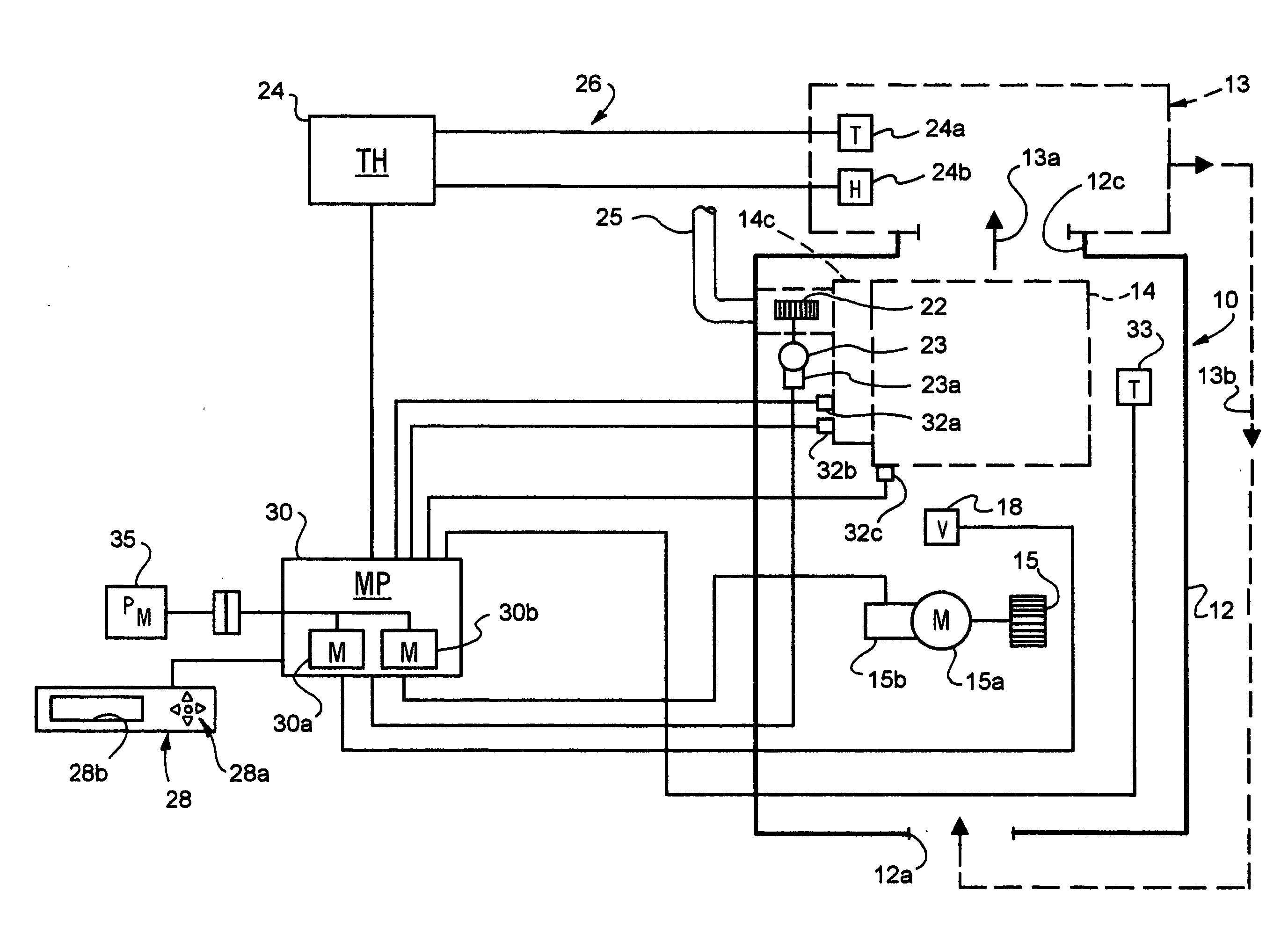
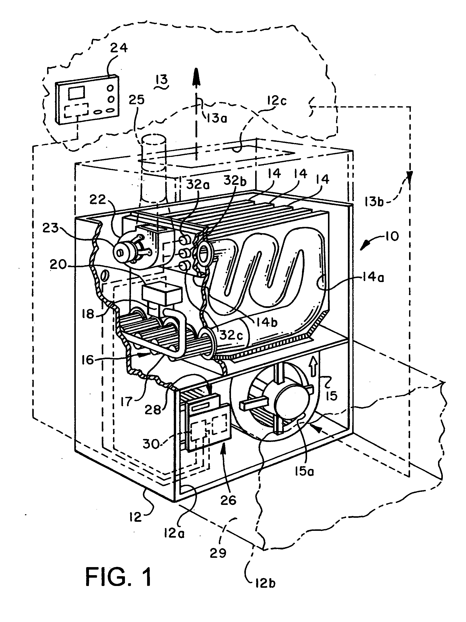
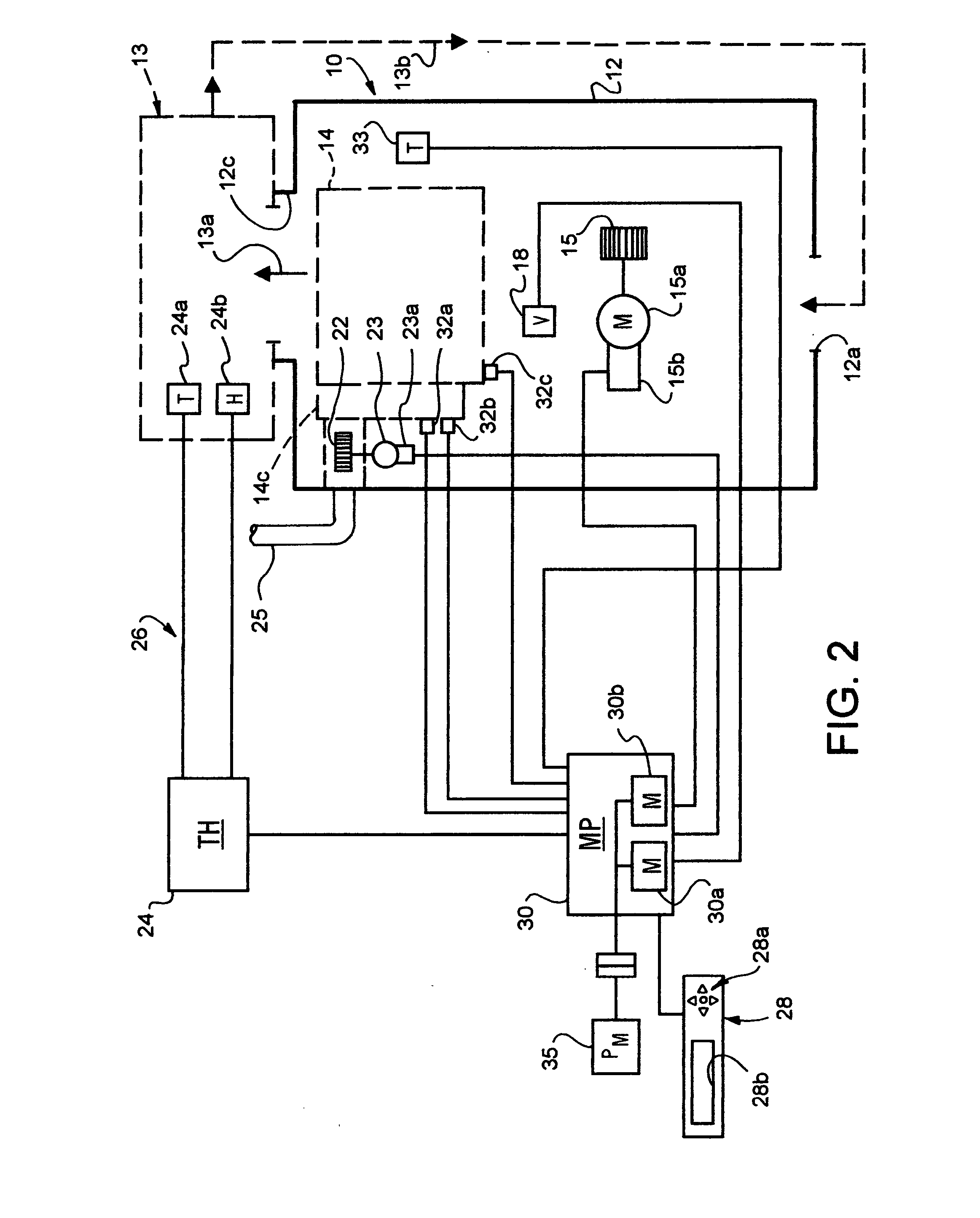
[0014]Referring to FIG. 1, there is illustrated a combustion furnace operable by the method of the present invention and generally designated by the numeral 10. The furnace 10 is illustrated as including a generally rectangular boxlike cabinet 12 having an air inlet opening 12a adapted to be connected to a return air duct 12b. Cabinet 12 also includes a discharge air opening 12c for discharging air through suitable ducting to an enclosed space 13. Airflow to and from the furnace 10 is via suitable ducting and in accordance with the direction of flow indicated by the arrows 13a and 13b. Combustion furnace 10 includes plural side-by-side gaseous fuel fired heat exchangers 14,...


PUM


Abstract

In a multistage combustion furnace having a motor driven inducer blower and a pressure sensing device or set of switches for sensing pressure in the combustion gas flowpath through the furnace, a high firing rate blower speed and low firing rate blower speed are set based on the blower speed setting required for a medium firing rate. Each particular furnace, having its own pressures and combustion gas resistance to flow characteristics, may be provided with a database of inducer blower motor speeds required to achieve predetermined pressures in the combustion gas flowpath for a variety of combustion gas venting systems generating such resistance.

Description

BACKGROUND OF THE INVENTION[0001]Efficient combustion furnaces for heating, ventilating and air conditioning (HVAC) equipment applications are typically provided with a motor driven so-called ventilating or inducer blower which draws air through the combustion passageways of the furnace heat exchanger to improve the efficiency of the combustion and heat transfer processes and to prolong the life of the furnace. Selection of the proper speeds of the inducer blower drive motor for multistage combustion furnaces, in particular, has been a somewhat nettlesome problem. Combustion furnaces which include electronic controls have been developed wherein the inducer blower motor speed is controlled based on opening and closing of pressure switches which measure the pressures developed by the inducer blower at one or more particular points in the air flowpath.[0002]Moreover, so-called learning algorithms have been developed which require setting a blower default speed for multistage furnaces f...

Claims


Application Information

Patent Timeline
IPC IPC(8): F24H9/20F23N3/08H02P1/04
CPCF23N3/002F23N3/082F23N5/242F23N2023/46F24H9/2085F23N2033/04F23N2037/10F23N2041/06F24H3/087F23N2025/06F23N2223/46F23N2225/06F23N2233/04F23N2237/10F23N2241/06F23N3/005F24H15/242F24H15/414F24H15/36F24H15/395F24H15/31F24H15/35F24H15/254
Inventor HUGGHINS, GORDON JEFFREYKOWALSKI, STEPHENROYCROFT, ROBERT G.
Owner TRANE INT INC
Why Eureka
Try Eureka