Camshaft phaser wiper seal

a camshaft and wiper technology, applied in the direction of engine seals, valve arrangements, machines/engines, etc., can solve the problems of difficult and time-consuming to reliably install backing springs, excessive load may be applied to backing springs, and difficult to correctly arrange backing springs, etc., to achieve better wear characteristics, reduce manufacturing costs and assembly cycle time, the effect of reducing the cos

Inactive Publication Date: 2009-02-19
DELPHI TECH INC
View PDF4 Cites 13 Cited by
  • Summary
  • Abstract
  • Description
  • Claims
  • Application Information

AI Technical Summary

Benefits of technology

[0013]Briefly described, a wiper seal subassembly for preventing leakage of oil between advance and retard chambers formed between rotor vanes and stator lobes in a vane-type camshaft phaser in accordance with the invention combines a backing spring and a sealing element in a pre-assembled unit. The wiper seal subassembly is provided at the tip of each rotor vane and / or stator lobe of a vane-type camshaft phaser. The vane-type camshaft phaser includes a rotor having a plurality of vanes disposed in a stator having a plurality of lobes, the interspersion of vanes and lobes defining a plurality of alternating valve timing advance and valve timing retard chambers with respect to the engine crankshaft. During rotation of the rotor within the stator, the tips of the vanes sweep past concave cylindrical walls of the stator, and the tips of the lobes sweep past convex cylindrical walls of the rotor hub. Each vane and lobe tip is provided with an axially extending groove. The wiper seal subassembly in accordance with the invention is disposed in the groove for wiping the opposing wall, such as the stator wall and / or rotor hub. The wiper seal subassembly in accordance with the invention is designed as a potential drop-in replacement for existing prior art wiper seals, thereby eliminating the need for changing the design of the vane and lobe tips.
[0014]The wiper seal subassembly in accordance with the invention includes a sealing element having integrated spring retention features. The spring retention features include undercut retention features, such as an overhanging edge, that prevent the backing spring from vertically detaching from the sealing element. The spring retention features further include sidewall tabs that prevent the backing spring from horizontally detaching from the sealing element.
[0017]By integrally molding spring retention features into the sealing element in accordance with the present invention, the manufacturing costs and assembly cycle time can be reduced compared to prior art wiper seals based on elimination of secondary machining operations, such as ultrasonic deformation, surface treatment, and elastomer insert molding steps. Lower cost materials that may also exhibit better wear characteristics against aluminum can be used in the wiper seal sub assembly in accordance with the present invention compared to prior art wiper seals due to the elimination of material exposure to surface treatment and elastomer insert molding pressures and temperatures. Furthermore, providing the wiper seal subassembly as a pre-assembled one-piece unit in accordance with the invention is beneficial for the assembly of the wiper seal subassembly in a camshaft phaser, since the backing spring is reliably arranged relative to the sealing element and will not become detached form the sealing element during installation in a groove of a rotor vane or stator lobe.

Problems solved by technology

It is difficult and time consuming to reliably install a backing spring that is not fixed to a wiper blade in valve timing adjusting devices, such as a camshaft phaser, since the backing spring may fall out of the wiper blade or it may be difficult to correctly arrange the backing spring relative to the wiper blade.
In cases where the wiper blade and the backing spring are fixed to each other by spot welding or screwing to avoid problems of installing two separate parts, an elastic coefficient of the backing spring is increased during insertion into axial directional grooves included in the rotor vane or stator lobe and, consequently, an excessive load may be applied to the backing spring.
While these known wiper seals may reliably prevent a backing spring from detaching from a wiper blade without applying a excessive load to the backing spring, secondary machining steps are needed to complete the wiper blade assembly in order to retain the backing spring, and often no preassembly of the wiper blade-backing spring unit is possible.
This configuration requires two separate manufacturing steps, one successive assembly step, and two different materials to provide a one-piece wiper seal subassembly, creating undesired manufacturing and subassembly costs as well as complexity.

Method used


Image

  • Camshaft phaser wiper seal
  • Camshaft phaser wiper seal
  • Camshaft phaser wiper seal

Examples


first embodiment

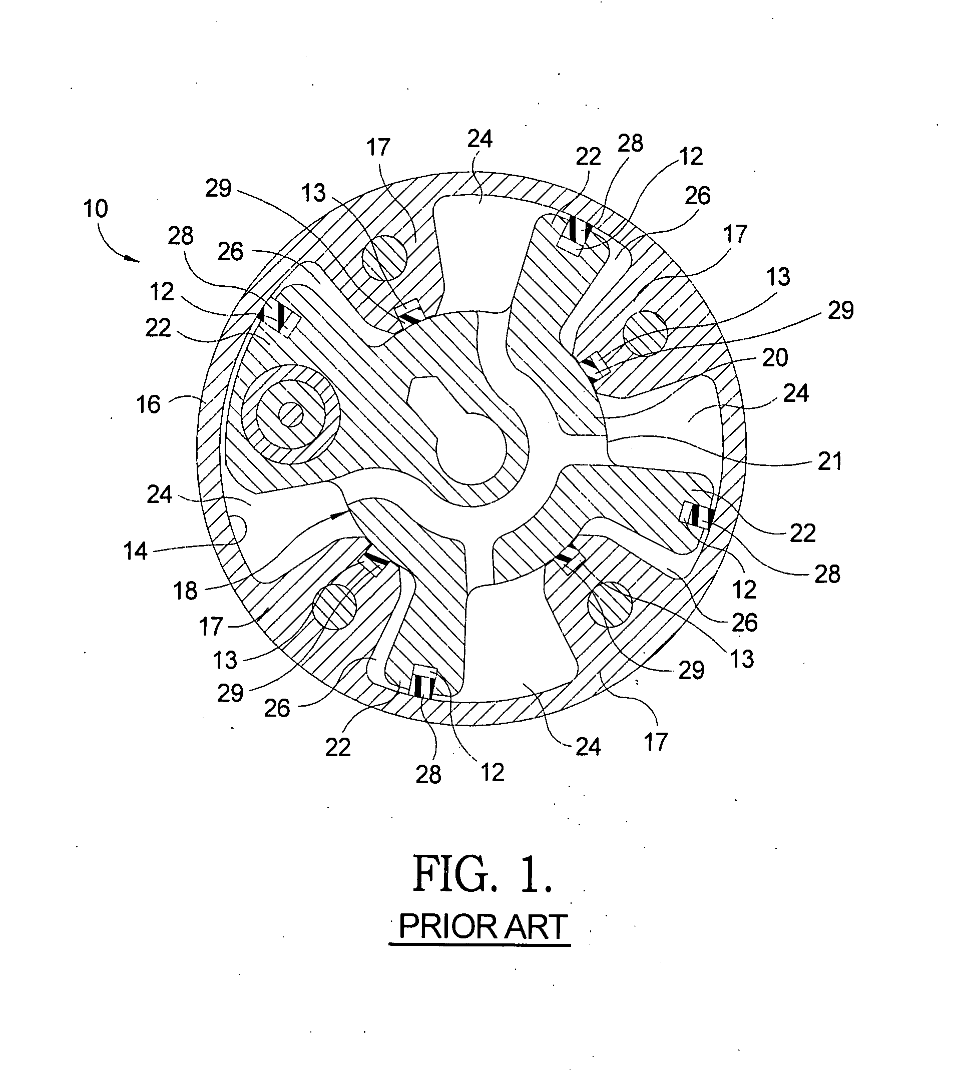
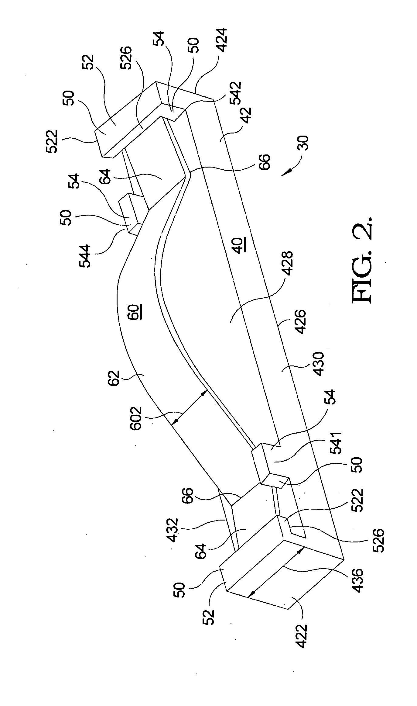
[0028]Referring to FIGS. 2 through 4, a wiper seal subassembly 30 in accordance with the invention for disposal in rotor vanes and / or stator lobes of a vane-type camshaft phaser, such as camshaft phaser 10 shown in FIG. 1, is shown. It should be recognized that wiper seal subassembly 30, as well as alternate designs 70 and 80 of wiper seal subassembly 30, disclosed herein are equally suitable as a direct replacement for either of prior art vane seal element 28 or prior art lobe seal element 29 without modification of prior art vane groove 12 and prior art lobe groove 13 in accordance with the invention as described herein below.

[0029]The wiper seal subassembly 30 includes a sealing element 40 and a backing spring 60. Sealing element 40 includes a body 42 that extends longitudinally from a first end 422 to a second end 424 for a length 434, that extends transversely from a front edge 430 to a back edge 432 for a width 436, and that has an outer surface 426 and an inner surface 428. B...

second embodiment

[0037]Referring now to FIG. 5, wiper seal subassembly 70, an alternative design of wiper seal subassembly 30, is shown according to the invention. As can be seen, overhanging edge 522 of undercut retention feature 52 is designed as an angled lead in. Furthermore, the undercut 526 of the undercut retention feature 52 is angled to assist focusing backing spring 60 in position. First sidewall tab 541 and fourth sidewall tab 544 are shown to have a circular shape and to extend along edges 430 and 432, respectively, for a longer distance than sidewall tabs 541 and 544 shown in FIGS. 2 through 4.

third embodiment

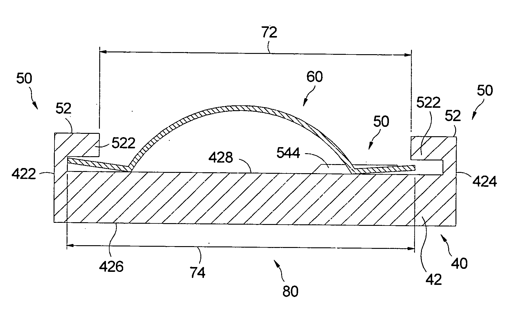
[0038]Referring now to FIGS. 6 and 7, wiper seal subassembly 80, an alternative design of wiper seal subassembly 30, is shown according to the invention. First sidewall tab 541 and fourth sidewall tab 544 are shown to have a: polygonal shape and to extend along edges 430 and 432, respectively, for a longer distance than sidewall tabs 541 and 544 shown in FIGS. 2 through 4. Undercut retention features 52 have a hexagonal cross-section contrary to the rectangular cross-section shown in FIGS. 2-4, which results in material savings.

[0039]As can be seen in FIG. 7, the inside length 72 between the undercut retention feature 52 at first end 422 and the opposite undercut retention feature 52 at second end 424 is smaller than the length 74 of relaxed backing spring 60 to prevent backing spring 60 from disengaging from sealing element 40 after insertion of backing spring 60 into sealing element 40.

[0040]Backing spring 60 including cutouts 68 in central section 62, as shown in FIG. 5, may be u...


PUM


Abstract

A wiper seal subassembly for disposal in rotor vanes or stator lobes of a vane-type camshaft phaser comprises a backing spring and a sealing element. The sealing element includes spring retention features that loosely retain the backing spring and that are integrally molded into the sealing element. The spring retention features include undercut retention features, such as an overhanging edge, that prevent the backing spring from vertically detaching from the sealing element. The spring retention features further include sidewall tabs that prevent the backing spring from horizontally detaching from the sealing element. The sealing element is formed from a plastic composite material during an injection molding process using a simple injection mold tooling design. The single-piece wiper seal subassembly is provided at the tip of each rotor vane and / or stator lobe of a vane-type camshaft phaser for varying the timing of combustion valves in an internal combustion engine.

Description

TECHNICAL FIELD[0001]The present invention relates to hydraulic valve timing devices of internal combustion engines; more particularly, to vane-type camshaft phasers; and most particularly, to a low cost wiper seal subassembly for disposal in rotor vanes and / or stator lobes of a camshaft phaser.BACKGROUND OF THE INVENTION[0002]Camshaft phasers for varying the phase relationship between the crankshaft and a camshaft of an internal combustion engine are well known. A prior art vane-type phaser generally comprises a plurality of outwardly extending vanes on a rotor interspersed with a plurality of inwardly extending lobes on a stator, forming alternating advance and retard chambers between the vanes and lobes. Engine oil is supplied via a multiport oil control valve (OCV), in accordance with an engine control module, to either the advance or retard chambers as required to meet current or anticipated engine operating conditions.[0003]In a typical prior art vane-type camshaft phaser, als...

Claims


Application Information

Patent Timeline
Patent Type & Authority Applications(United States)
IPC IPC(8): F16J15/00
CPCF01L2001/34479F01L1/3442
Inventor DEANGELIS, GARY J.RANELLI, DAVID J.WEISS, AMANDA M.
Owner DELPHI TECH INC
Why Eureka
Try Eureka