Projection optical system, exposure apparatus, and exposure method

a projection optical system and exposure apparatus technology, applied in the field of projection optical systems, exposure apparatuses, exposure methods, etc., can solve the problems of increasing reflection loss occurring at the optical surface, and the projection optical system cannot obtain a large effective numerical aperture at the image side, so as to achieve high accuracy, reduce the accuracy of alignment, and improve the effect of accuracy

Inactive Publication Date: 2009-02-19
NIKON CORP
View PDF11 Cites 23 Cited by
  • Summary
  • Abstract
  • Description
  • Claims
  • Application Information

AI Technical Summary

Benefits of technology

[0022]The immersion projection optical system according to a typical aspect of the present invention has, for example, a catadioptric and off-axis structure, in which a light emitting surface of a refractive optical element that is arranged nearest to an imaging position is rotationally-asymmetric with respect to an optical axis of the projection optical system according to the shape of an effective projection region formed on an image surface. More specifically, the light emitting surface of the refractive optical element is substantially symmetric with respect to two axial directions that are perpendicular to each other on the image surface. A central axis of the light emitting surface and a central axis of a circle corresponding to a circumference of a light entering surface of the refractive optical element substantially coincide with each other. The central axis of the light emitting surface is decentered along one of the two axial directions with respect to the optical axis.
[0023]As a result, the light emitting surface of the refractive optical element that is arranged nearest to the imaging position in the projection optical system of the present invention is rotationally-asymmetric in accordance with the shape of the effective projection region. The projection optical system of the present invention reduces the portion of an image space filled with liquid (immersion liquid). Further, the exposure apparatus and the exposure method of the present invention use a high-resolution immersion projection optical system, which reduces a portion of an image space filled with liquid, and enable a micropattern to be projected and exposed with a high accuracy without enlarging a substrate stage of the projection optical system or lowering the accuracy of an alignment optical system of the projection optical system. Consequently, this produces a satisfactory microdevice with high accuracy.

Problems solved by technology

This increases reflection loss occurring at an optical surface.
As a result, the projection optical system cannot obtain a large effective numerical aperture at its image side.

Method used


Image

  • Projection optical system, exposure apparatus, and exposure method
  • Projection optical system, exposure apparatus, and exposure method
  • Projection optical system, exposure apparatus, and exposure method

Examples


first example

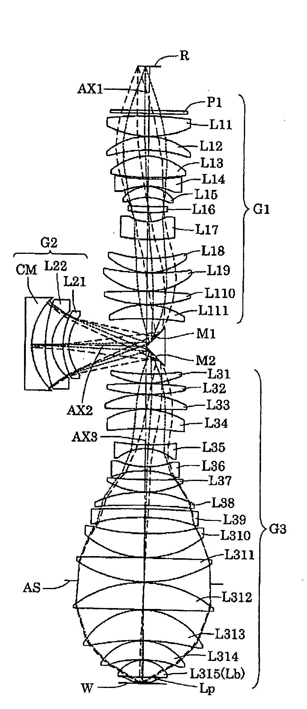
[0060]FIG. 4 shows a lens structure of a projection optical system according to a first example of the present embodiment. As shown in FIG. 4, the first imaging optical system G1 included in the projection optical system PL of the first example includes a plane parallel plate P1, a biconvex lens L11, a positive meniscus lens L12 having a convex surface at its reticle side, a biconvex lens L13, a biconcave lens L14 having an aspherical concave surface at its reticle side, a positive meniscus lens L15 having a convex surface at its reticle side, a positive meniscus lens L16 having a concave surface at its reticle side, a negative meniscus lens L17 having a concave surface at its reticle side, a positive meniscus lens L18 having an aspherical concave surface at its reticle side, a positive meniscus lens L19 having a concave surface at its reticle side, a biconvex lens L110, and a positive meniscus lens L111 having an aspherical concave surface at its wafer side, which are arranged sequ...

second example

[0067]FIG. 6 shows a lens structure for a projection optical system according to a second example of the present embodiment. As shown in FIG. 6, the first imaging optical system G1 in the projection optical system PL of the second example includes a plane parallel plate P1, a biconvex lens L11, a positive meniscus lens L12 having a convex surface at its reticle side, a positive meniscus lens L13 having a convex surface at its reticle side, a biconcave lens L14 having an aspherical concave surface at its reticle side, a positive meniscus lens L15 having a convex surface at its reticle side, a positive meniscus lens L16 having a concave surface at its reticle side, a negative meniscus lens L17 having a concave surface at its reticle side, a positive meniscus lens L18 having an aspherical concave surface at its reticle side, a positive meniscus lens L19 having a concave surface at its reticle side, a biconcave lens L110, and a positive meniscus lens L111 having an aspherical concave su...


PUM


Abstract

An immersion projection optical system having, for example, a catadioptric and off-axis structure, reduces the portion of an image space filled with liquid (immersion liquid). The projection optical system, which projects a reduced image of a first plane onto a second plane through the liquid, includes a refractive optical element (Lp) arranged nearest to the second plane. The refractive optical element includes a light emitting surface (Lpb) shaped to be substantially symmetric with respect to two axial directions (XY-axes) perpendicular to each other on the second plane. The light emitting surface has a central axis (Lpba) that substantially coincides with a central axis (40a) of a circle (40) corresponding to a circumference of a light entering surface (Lpa) of the refractive optical element. The central axis of the light emitting surface is decentered in one of the two axial directions (Y-axis) from an optical axis (AX).

Description

TECHNICAL FIELD[0001]The present invention relates to a projection optical system, an exposure apparatus, and an exposure method, and more particularly, to a projection optical system optimal for an exposure apparatus used to manufacture microdevices, such as semiconductor devices and liquid crystal display devices, through a photolithography process.BACKGROUND ART[0002]An exposure apparatus projects and exposes an image of a pattern of a mask (or a reticle) on a photosensitive substrate (e.g., wafer or a glass plate coated by a photoresist). More specifically, the exposure apparatus uses a projection optical system to project and expose the image in a photolithography process, in which semiconductor devices or the like are manufactured. The projection optical system is required to have a higher resolution due to the increasing level of integration of semiconductor devices or the like manufactured with the exposure apparatus.[0003]To improve the resolution of the projection optical ...

Claims


Application Information

Patent Timeline
Patent Type & Authority Applications(United States)
IPC IPC(8): G03B27/54
CPCG02B1/06G02B17/0892G02B21/33G03F7/702G03F7/70341G02B17/08G03F7/70225G03F7/2041G03F7/70275H01L21/0273H01L21/0274G03F7/70725
Inventor OMURA, YASUHIROOKADA, TAKAYANAGASAKA, HIROYUKI
Owner NIKON CORP
Why Eureka
Try Eureka