Control system and method for controlling an air handling fan for a vent hood

a technology for controlling systems and air handling fans, which is applied in the direction of static/dynamic balance measurement, instruments, stoves or ranges, etc., can solve the problems of wasting energy, unable to turn on the vent hood or increase the speed, and often too busy with other tasks to achieve the effect of preventing chattering and buzzing relays, promoting proper electrical components, and avoiding repetitive, unnecessary and sometimes harmful switching of the speed of the fan

Inactive Publication Date: 2009-02-19
MAXITROL
View PDF17 Cites 22 Cited by
  • Summary
  • Abstract
  • Description
  • Claims
  • Application Information

AI Technical Summary

Benefits of technology

[0009]By utilizing the deadband range to computer the deadband setpoint, the subject invention provides a method that helps eliminate repetitive, unnecessary, and sometimes harmful switching of the speed of the fan. As the switching of the motor speed may cause damage to various electrical components, such as relays and transistors, the method serves to prevent quick switching of the fan back to the first speed. The method also promotes proper operation of electrical components, e.g., preventing chattering and buzzing relays.

Problems solved by technology

As such, these vent hoods exhaust not only uncomfortably warm air, but also the smoke that often accompanies food preparation.
Unfortunately, these manually operated vent hoods are often left on, even when not needed, and therefore wasted energy.
Furthermore, a user, e.g., a cook, are often too busy with other tasks to turn the vent hood on or increase its speed from low to high.
Moreover, automatically operated vent hoods often switch erratically between different speeds based on a sudden cooling that occurs when the fan is turned on or is increased form a low speed to a high speed.

Method used


Image

  • Control system and method for controlling an air handling fan for a vent hood
  • Control system and method for controlling an air handling fan for a vent hood
  • Control system and method for controlling an air handling fan for a vent hood

Examples


Embodiment Construction

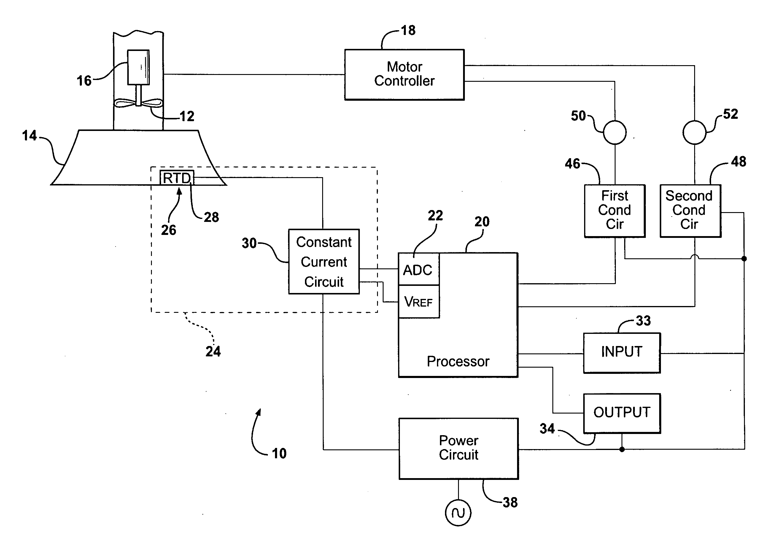
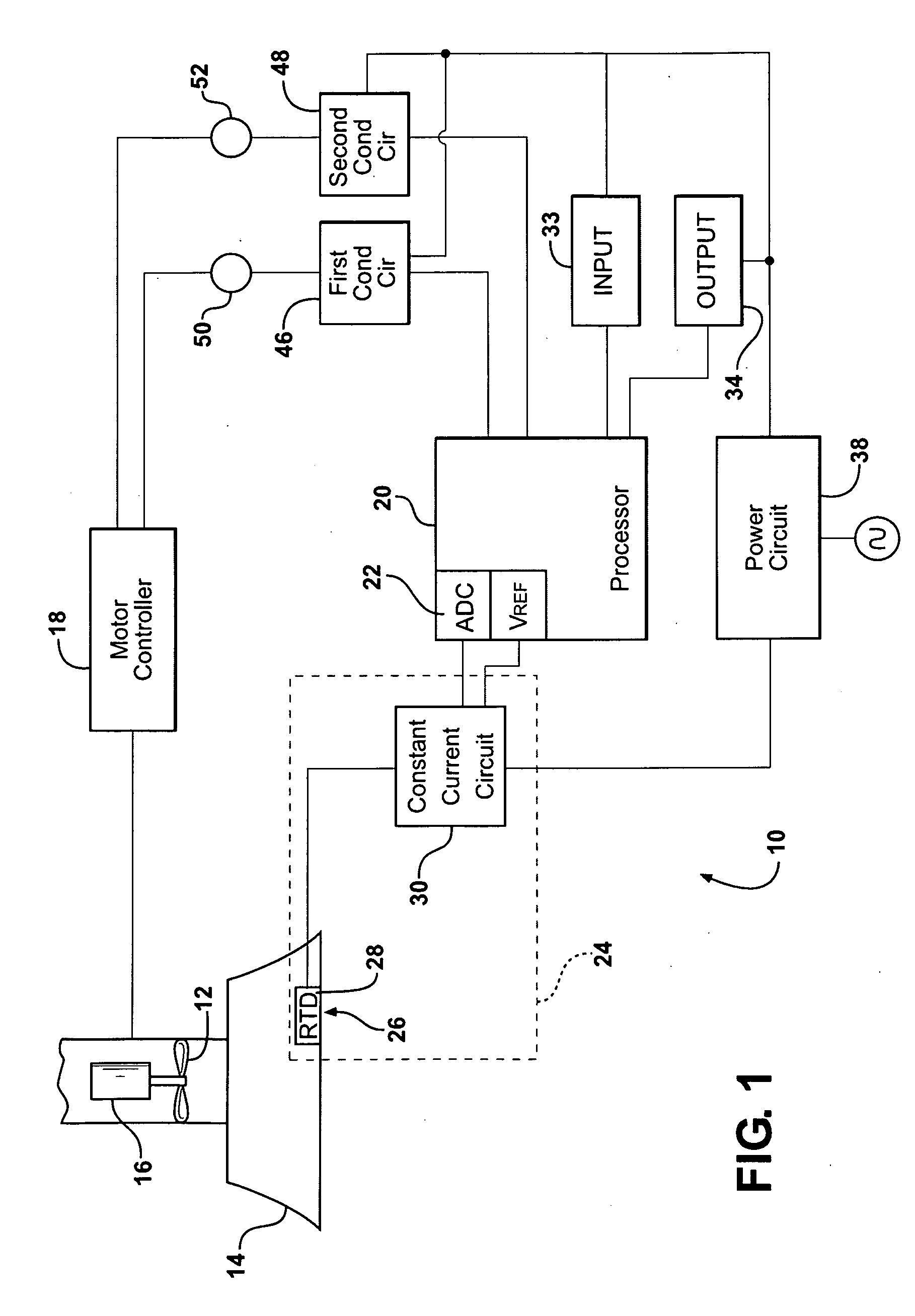
[0017]Referring to the Figures, wherein like numerals indicate corresponding parts throughout the several views, a control system 10 is shown for controlling an air handling fan 12 for a vent hood 14. The vent hood 14 may be positioned in a kitchen, particularly above a cooking surface. An electric motor 16 operatively connected to the fan 12 for turning the fan 12, as is well known to those skilled in the art. The fan 12 generates an airflow to move air though the vent hood 14 and, typically, to exhaust the air to the atmosphere.

[0018]A motor controller 18 is electrically connected to the electric motor 16 for controlling the application of electric current to the electric motor 16. In the preferred embodiment, the motor controller 18 is a variable speed drive capable of operating the motor 16 at a variety of speeds. Consequently, the speed of the fan 12 and the rate of air flow generated by the fan 12, are also variable. More preferably, the motor controller 18 is a variable frequ...


PUM


Abstract

A system and method of controlling a variable speed air handling fan for a vent hood includes a temperature sensor and a processor. Speed setpoints and a deadband range are received from a user by the processor. The processor computes deadband setpoints and receives a temperature from the temperature sensor. The processor is in communication with a motor controller for controlling the speed of the fan. The processor changes the speed of the fan when the temperature rises above a certain setpoint. However, the processor will not change the speed of the fan back to its previous speed until the temperature falls below the deadband setpoint that corresponds to the certain setpoint.

Description

CROSS REFERENCE TO RELATED APPLICATION[0001]This application claims the benefit of U.S. Provisional Application No. 60 / 956,548 filed Aug. 17, 2007.BACKGROUND OF THE INVENTION[0002]1. Field of the Invention[0003]The subject invention relates to a system and a method for operating air handling fans for vent hoods.[0004]2. Description of the Related Art[0005]Ventilation hoods, i.e., vent hoods, are commonly used in buildings to ventilate air to the outside. These vent hoods are often installed in kitchens above cooking ranges, both in commercial and residential applications. As such, these vent hoods exhaust not only uncomfortably warm air, but also the smoke that often accompanies food preparation.[0006]In the past, these vent hoods were mostly manually operated. That is, a user would turn a fan on using a switch or button and turn it off when complete. Unfortunately, these manually operated vent hoods are often left on, even when not needed, and therefore wasted energy. Furthermore, ...

Claims


Application Information

Patent Timeline
Patent Type & Authority Applications(United States)
IPC IPC(8): G05B15/00F24C15/20G05D23/00
CPCG05D23/2415F24C15/2021G05D23/1912G05D23/24
Inventor HANAWALT, NICHOLAS ROTH
Owner MAXITROL
Why Eureka
Try Eureka