Time delay for sample collection in chromatography systems

a chromatography system and sample technology, applied in the field of compound detection and collection system, can solve the problems of no reference discloses, or even addresses, and high waste solvent production, and achieve the effect of slow effective process time for samples and high detection efficiency

Active Publication Date: 2009-02-26
THAR INSTR
View PDF15 Cites 23 Cited by
  • Summary
  • Abstract
  • Description
  • Claims
  • Application Information

AI Technical Summary

Benefits of technology

[0016]The preferred and alternative embodiments compensate for the split flowstream travel time and processing delays associated with a split stream detector so that the primary flowstream containing the separated compounds will reach the. Instead of a delay loop into a flowstream.

Problems solved by technology

While process and collection speeds are faster than LC, drawbacks to HPLC include high waste solvent production and slow effective process time for samples due to removal of solvent and water from collected sample fractions.
Neither reference discloses, or even addresses, the problems associated with a delay caused by sensing and processing of an upstream detector and the travel time for a flowstream on a split to the detector prior to a collection system.
Although HPLC is an advancement over LC, similar problems exist for collection of sample fractions.
Further, even more drawbacks exist to the current use of preparative HPLC.
This can lead to very large volumes of waste mobile phase being generated in normal operation of the system.
A problem in all of the above-referenced separation technologies, but especially HPLC and SFC is when the chromatographic system is combined with a mass spectrometer on a split after the column but upstream from a collection system.
Causes for the delay include operations for sensing, analyzing, and processing time in the mass spectrometer as well as the computer processing for a controller.
These processing delays can be caused by complexity of the compound that creates the signal for the spectrometer to analyze, the complexity of rules for analyzing and presenting the signal, complexity or interference of other signals in the system caused by background interference from other components in the flowstream, and speed of the processor and bus in the instruments and in the controller.
However this is not always the case, and furthermore when beginning a sample run the delay is an unknown parameter that can adversely affect collection of the components.
A special problem in SFC in compensating for delay is that linear flowrates through tubes are generally significantly higher than HPLC and LC due to the extremely high flowstream pressures in SFC.
The same problems apply to SFE.
The use of wide-bore tubing in SFC is undesirable because of the problems associated with dispersion of the peak that would occur after the detector has defined the peak in the stream.
Using small-bore tubing in SFC creates problems as well, which includes adding up to 20 or 30 meters of tubing for a delay compensation since the flowstream velocity is measured on the order of meters / second.
Further, the extremely fast flowstream for a great distance can itself cause pressure and dispersion problems of the separated fraction in the flowstream.
The flowrate for this part of the flowstream is virtually impossible to calculate as the stream changes its composition within the tube.

Method used


Image

  • Time delay for sample collection in chromatography systems
  • Time delay for sample collection in chromatography systems
  • Time delay for sample collection in chromatography systems

Examples


Embodiment Construction

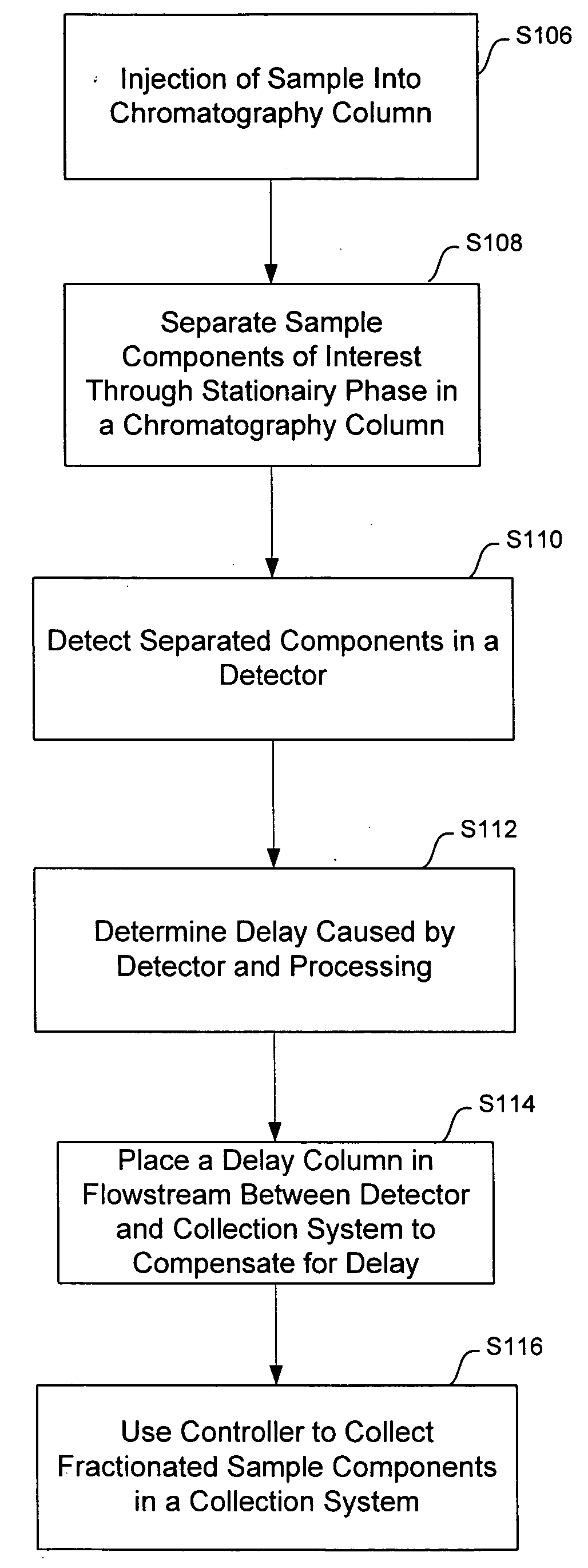
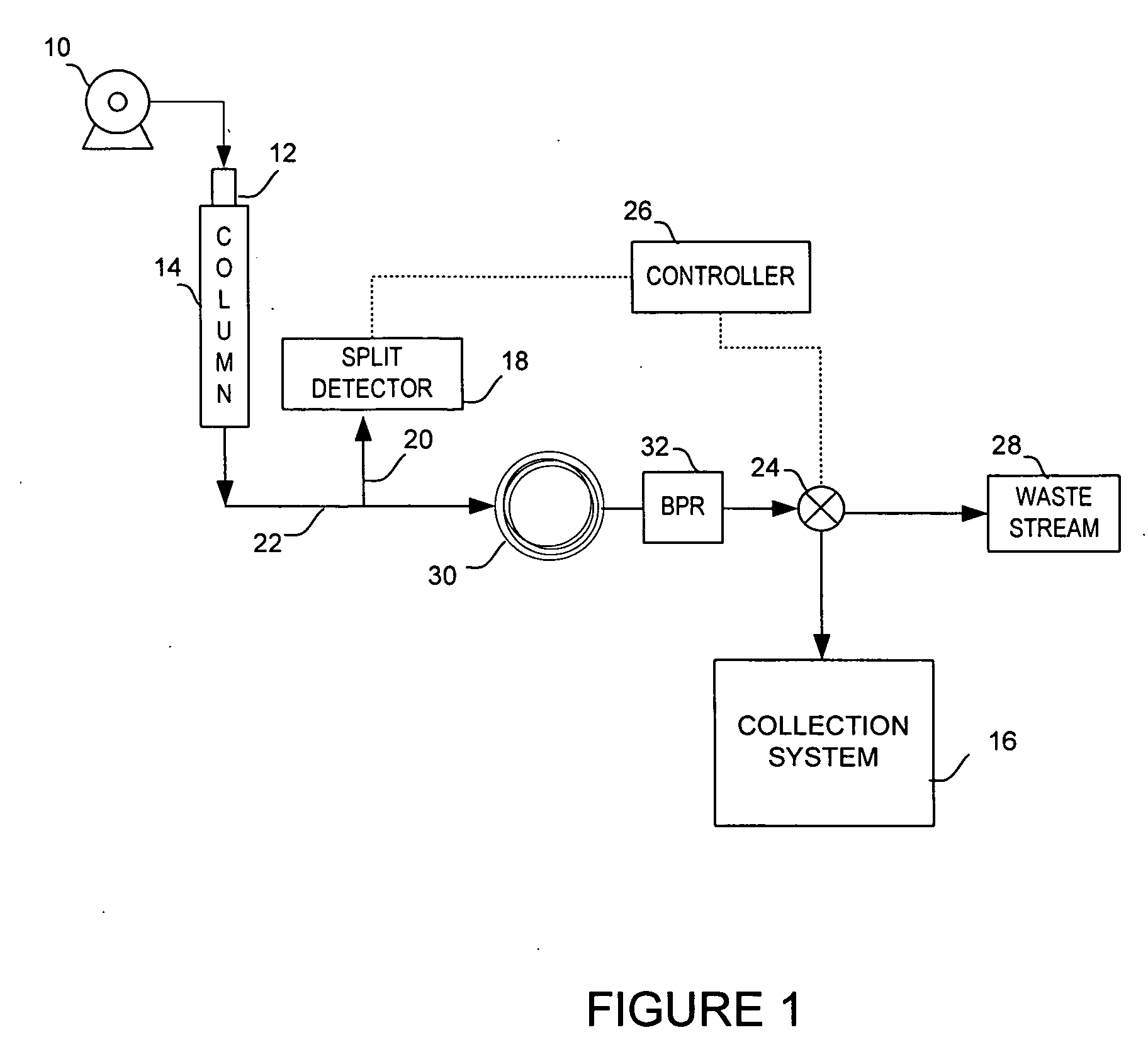
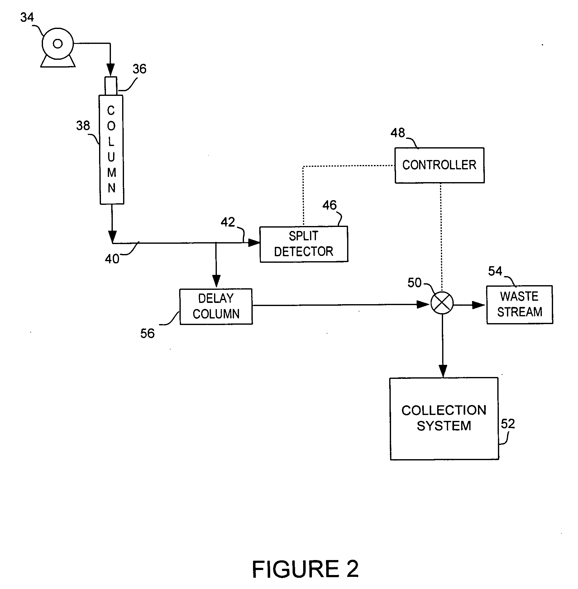
[0023]The preferred and alternative embodiments are used in the collection process of sample components, commonly called fractions, that have eluted from a chromatography column. The preferred embodiment is a method and system of using a chromatography packed column with known phase and flow parameters that adds delay of the flowstream prior to entering a collection system directional valve or other re-directing mechanism. In FIG. 2, an exemplary chromatography system capable implementing the preferred embodiment is illustrated. The system may use liquid chromatography (LC), high performance liquid chromatography (HPLC), supercritical fluid chromatography, or supercritical fluid extraction technology.

[0024]The preferred embodiment uses pump system 34 may include multiple pumps with mixtures of modifier liquid and gas, depending upon the type of chromatography system used. Pump 34 feeds a mobile phase under pressure into chromatography column 38. Injection valve 36 provides the means...


PUM

PropertyMeasurementUnit
diameteraaaaaaaaaa
diameteraaaaaaaaaa
diameteraaaaaaaaaa

Abstract

A system and process for chromatography that uses a chromatography column to separate components from a sample received into the column in a mobile phase flowstream and places a second chromatography column between a detector and a collection system that compensates the timing of fraction collection for a delay caused by processing the collection signals generated by the detector. The device and process of the preferred and alternative embodiments add a delay into the flowstream of a chromatographic system, such as LC, HPLC, and SFC. Sample fractions are collected from sample component concentration peaks based upon the chromatographic elution of the sample components.

Description

FIELD OF THE INVENTION[0001]The present invention relates to a compound separation and collection system, and more specifically compound detection and timing for collection in a chromatography system.BACKGROUND OF THE INVENTION[0002]In the technology of separation of compounds using chromatography, analyzing and collecting separated fractions of chemical compounds have advanced to processes and systems that vary greatly in process, instruments, and production capability. Liquid chromatography uses a fluid, called a mobile phase, that is pumped through a chromatography separation column, called the stationary phase. A liquid sample containing one or more chemical compounds is injected into the mobile phase flowstream at the head of the column. Different compounds in the sample are delayed in the stationary phase for different time periods.[0003]The separated compounds exit the column according to different retention times. These separated compounds can be detected and graphed as a “p...

Claims


Application Information

Patent Timeline
Patent Type & Authority Applications(United States)
IPC IPC(8): B01D15/18
CPCG01N30/82
Inventor FOGELMAN, KIMBER D.WIKFORS, EDWIN E.CHEN, RUI
Owner THAR INSTR
Why Eureka
Try Eureka