Radiation detector

Inactive Publication Date: 2009-02-26
SHIMADZU CORP
View PDF6 Cites 11 Cited by
  • Summary
  • Abstract
  • Description
  • Claims
  • Application Information

AI Technical Summary

Benefits of technology

[0034]With the radiation detector according to this invention, the portion of the (radiation sensitive) semiconductor, located in the connection of the common electrode (for bias voltage application) to the lead wire (for bias voltage supply), is dented in a recessed form from other portions of the semiconductor, in a range short of the radiation detection effective area, and an insulating seat is disposed to

Problems solved by technology

However, the conventional radiation detector shown in FIG. 10 has a problem of performance degradation resulting from the lead wire 54 being connected to the common electrode 53.
That is, since a hard metal wire such as copper wire is used for the lead wire 54 for bias voltage supply, damage occurs to

Method used


Image

  • Radiation detector
  • Radiation detector
  • Radiation detector

Examples


embodiment 1

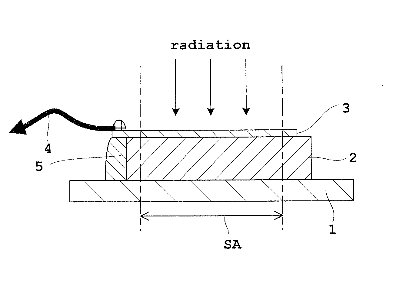
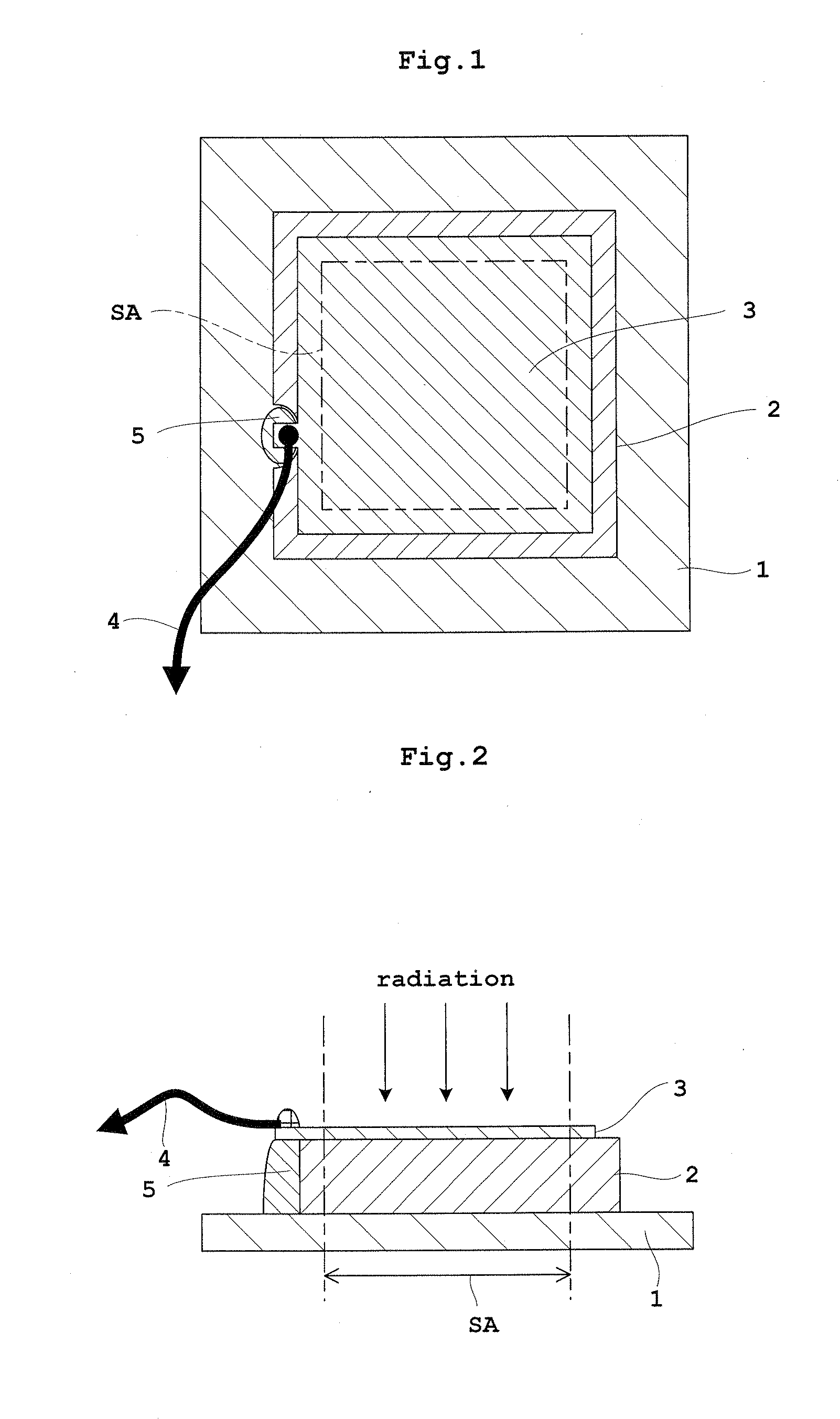
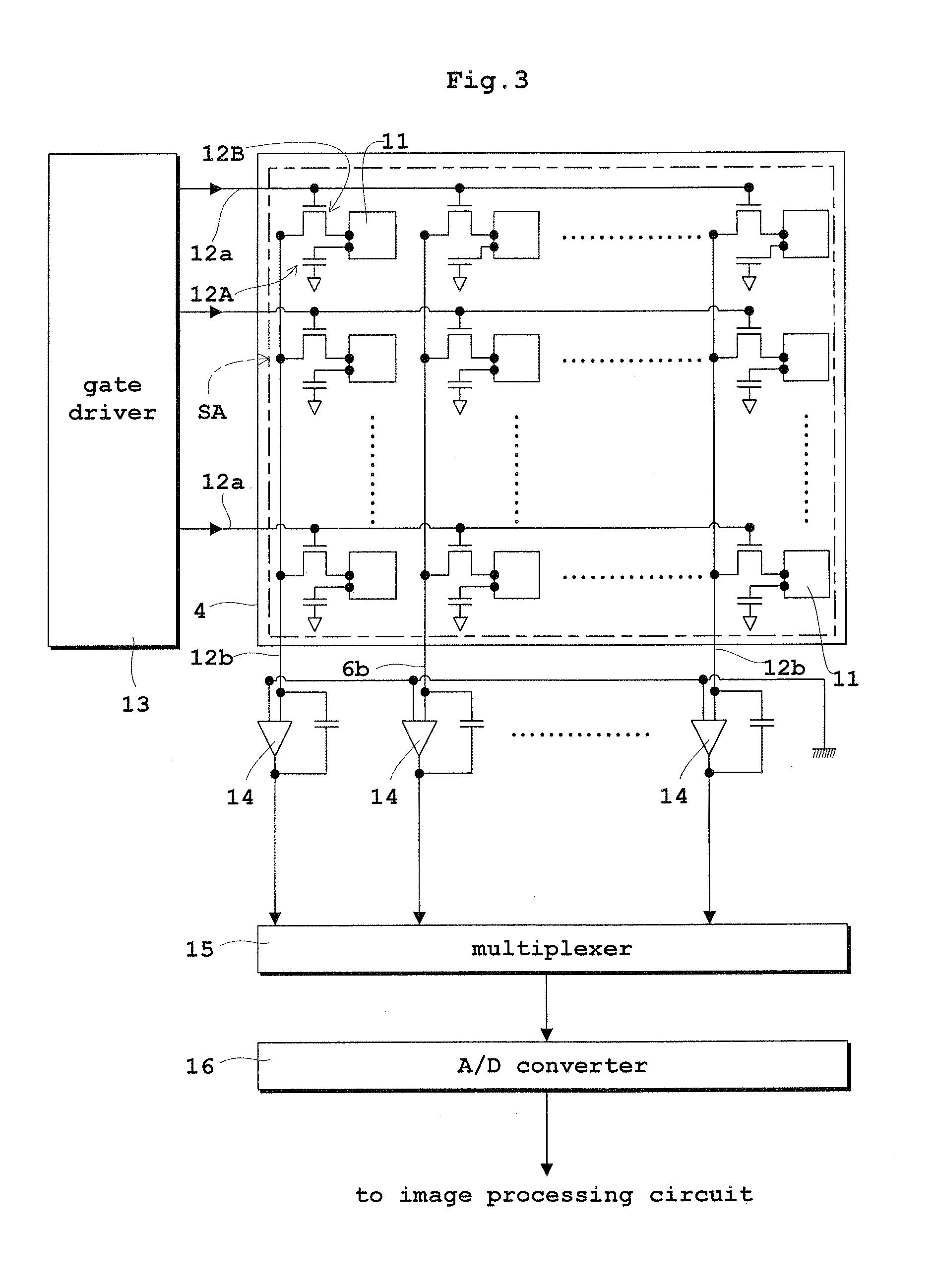
[0060]Embodiment 1 of this invention will be described hereinafter with reference to the drawings. FIG. 1 is a schematic plan view of a direct conversion type flat panel X-ray detector (hereinafter abbreviated as “FPD” where appropriate) in Embodiment 1. FIG. 2 is a schematic sectional view of the flat panel X-ray detector (FPD) in Embodiment 1. FIG. 3 is a block diagram showing an equivalent circuit of an active matrix substrate of the flat panel X-ray detector (FPD). FIG. 4 is a schematic sectional view of the active matrix substrate of the flat panel X-ray detector (FPD). FIG. 5 is a schematic sectional view of the flat panel X-ray detector (FPD) protected by an auxiliary plate in Embodiment 1. The flat panel X-ray detector (FPD) will be described as an example of radiation detector in Embodiment 1 and in Embodiment 2 to follow.

[0061]As shown in FIGS. 1 and 2, the FPD in Embodiment 1 includes an active matrix substrate 1, a radiation sensitive semiconductor 2 for generating elect...

embodiment 2

[0093]Next, Embodiment 2 of this invention will be described with reference to the drawings. FIG. 8 is a schematic sectional view of a flat panel X-ray detector (FPD) in Embodiment 2. Parts in common with foregoing Embodiment 1 are designated by the same reference numbers, and will not be described again, or shown in the drawings.

[0094]As shown in FIG. 8, the FPD in Embodiment 2 has a collimator 9 for preventing the radiation (X rays here) incident on the radiation detection effective area SA from impinging on edges of the common electrode 3 including the connection to the lead wire 4, and the seat 5. The collimator 9 corresponds to the collimator in this invention.

[0095]Electric fields formed by application of the bias voltage concentrate on the edges of the common electrode 3 and the seat 5. When the radiation impinges there, contingent strong currents could flow, that would cause a failure of the FPD (in particular, breakdown of TFTs 12B of the storing and reading electric circui...


PUM


Abstract

In a radiation detector according to this invention, a portion of a semiconductor, located in a connection of a common electrode to a lead wire, is dented in a recess form from other portions of a semiconductor, in a range short of a radiation detection effective area. An insulating seat is disposed to fill the portion located in the connection. The common electrode is formed to cover at least part of the seat. The lead wire is connected to a portion of the incidence surface of the common electrode located on the seat. Thus, the detector can avoid performance degradation resulting from connection of the lead wire to the common electrode, and avoid problems of heat deformation stress and radiation attenuation.

Description

TECHNICAL FIELD[0001]This invention relates to radiation detectors having a radiation sensitive semiconductor for generating electric charges upon incidence of radiation, for use in the medical, industrial, nuclear and other fields.BACKGROUND ART[0002]Radiation (e.g. X-ray) detectors include an “indirect conversion type” detector which once generates light upon incidence of radiation (e.g. X rays) and generates electric charges from the light, thus detecting the radiation by converting the radiation indirectly into the electric charges, and a “direct conversion type” detector which generates electric charges upon incidence of radiation, thus detecting the radiation by converting the radiation directly into the electric charges. The electric charges are generated by a radiation sensitive semiconductor.[0003]As shown in FIG. 10, a direct conversion type radiation detector has an active matrix substrate 51, a radiation sensitive semiconductor 52 for generating electric charges upon inc...

Claims


Application Information

Patent Timeline
IPC IPC(8): G01T1/24
CPCH01L27/14618H01L27/14676G01T1/244H01L31/0203H01L31/115H01L31/02002H01L2924/0002H01L2924/00H01L27/14H01L27/146H01L31/00
Inventor SATO, KENJISUZUKI, JUNICHIWATADANI, KOJI
Owner SHIMADZU CORP
Why Eureka
Try Eureka