
Organic electroluminescent display device having scattering member

a display device and electroluminescent technology, applied in the direction of discharge tube luminescnet screens, discharge tube/lamp details, electric discharge lamps, etc., can solve the problems of large loss of light, ineffective utilization of about 19% of the entire light emission quantity, etc., to achieve enhanced light waveguided extraction efficiency, less image blurring, and high light extraction efficiency

Inactive Publication Date: 2009-02-26
UDC IRELAND
View PDF13 Cites 64 Cited by
  • Summary
  • Abstract
  • Description
  • Claims
  • Application Information

AI Technical Summary

Benefits of technology

The present invention provides a light-emitting display device with high light extraction efficiency and less image blurring. This is achieved by improving the refractive index of the device, which results in better light waveguiding and reduced image blurring. The device includes an organic electroluminescent layer with a higher refractive index than air, and a scattering member on the upper electrode. The scattering member can be a light diffusing film or a color filter containing light scattering particles. The refractive index of the light scattering particles can be higher than the refractive index of the transparent resin composition in which they are embedded. The device can also have a low refractive index layer between the transparent substrate film and the light diffusing layer, or a hollow silica layer. The invention provides a more efficient and clearer display device with improved image quality.

Problems solved by technology

Thus, the majority of light is lost.
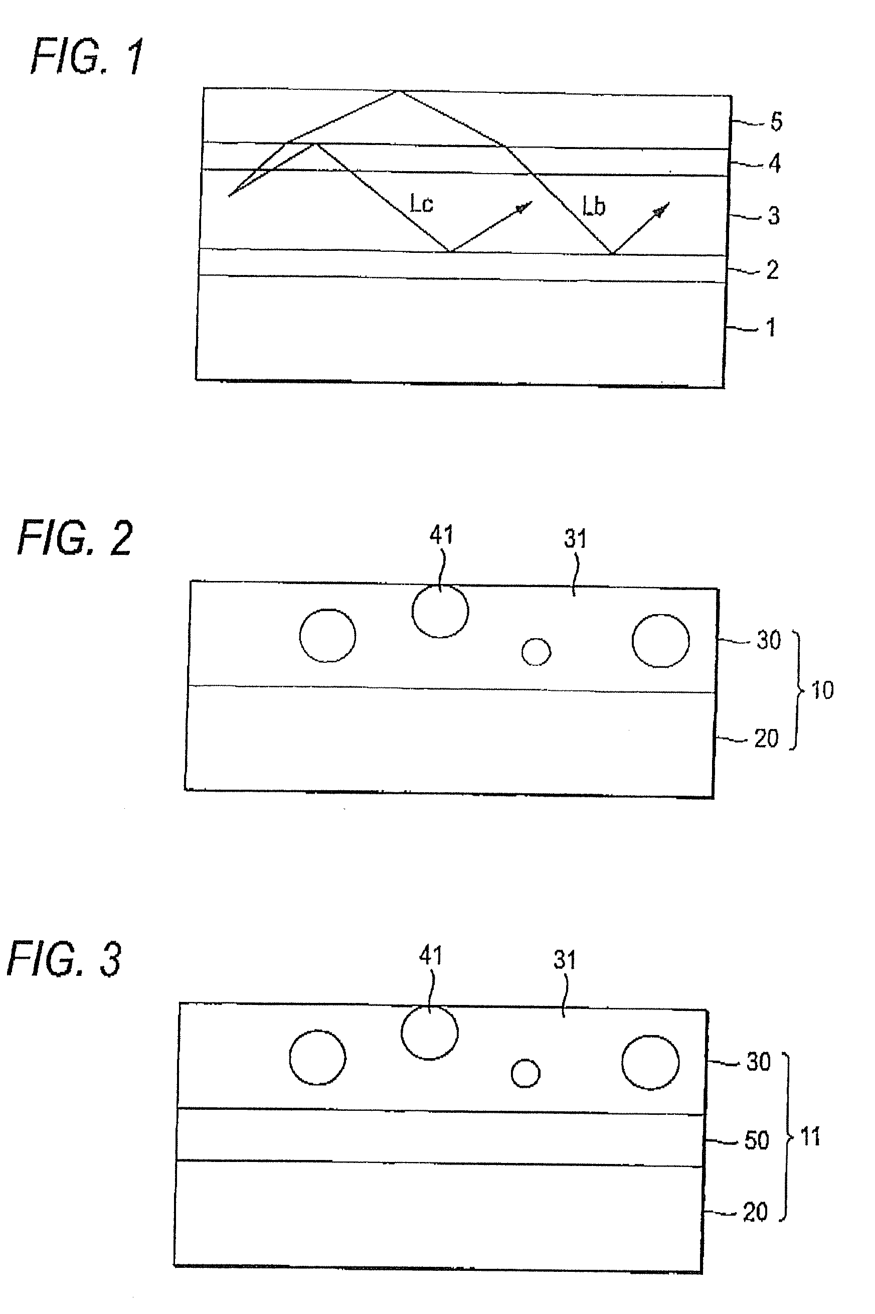
However, as shown in FIG. 1, light generated inside of the display device causes total reflection depending on the angle of light incident on the interface with an adjacent layer differing in the refractive index, and the light is entirely waveguided through the inside of the display derive and cannot be extracted to the outside (light of Lb and Lc in FIG. 1).
That is, only about 19% of the entire light emission quantity cannot be effectively utilized.
However, these methods have such a problem as that the processing is difficult or dielectric breakdown readily occurs at the time of passing a current.
However, occurrence of light scattering on the surface brings about a problem that light is greatly blurred and resolution deteriorates.
However, in this method, the refractive index of the material used as the base material of the light diffusing layer is from 1.5 to 1.6 and is improper for the efficient extraction of light waveguided through an organic layer+a transparent electrode.

Method used


Image

  • Organic electroluminescent display device having scattering member
  • Organic electroluminescent display device having scattering member
  • Organic electroluminescent display device having scattering member

Examples


example 1

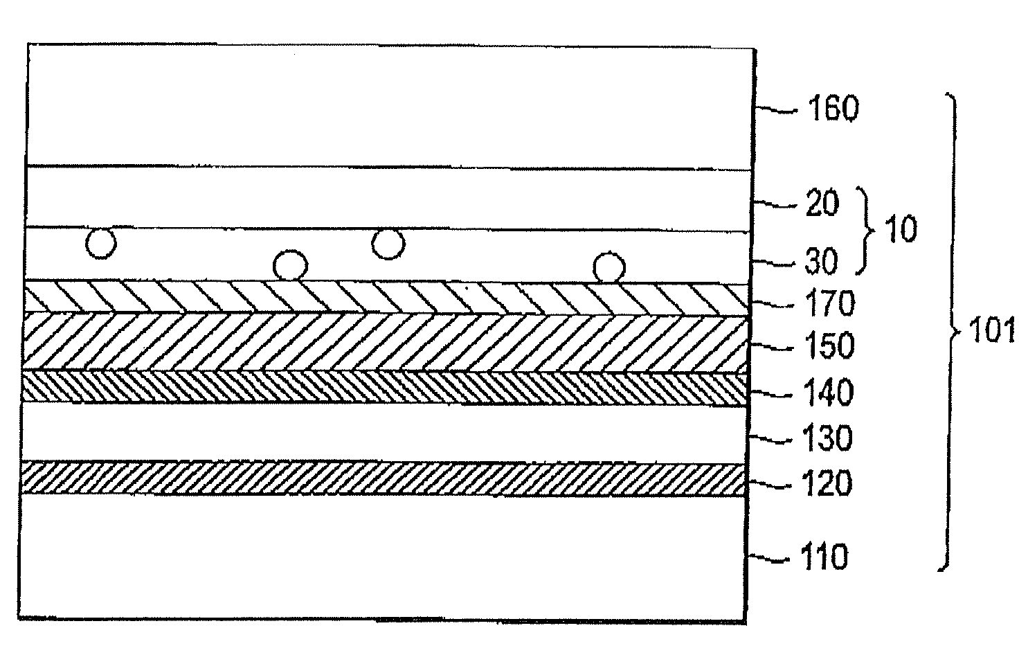
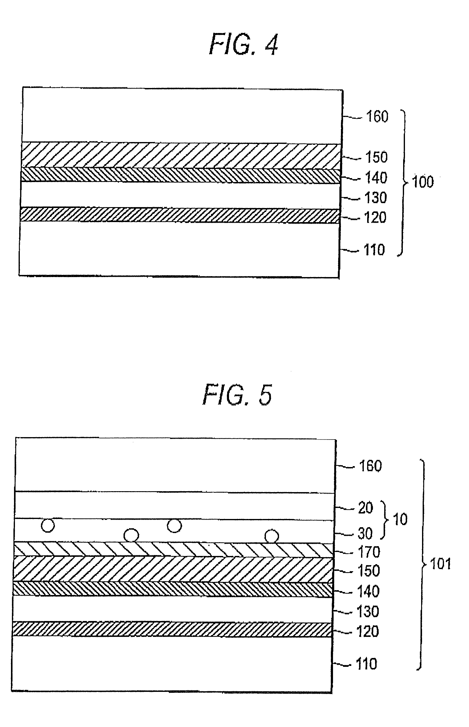
[0233]The embodiment 101 of Example 1 is shown in FIG. 5. The adhesive prepared above is coated on the barrier layer 150 to a thickness of 10 μm to provide an adhesion layer 170, and Light Diffusing Film 1 (10 in the Figure) is laminated thereon by arranging the light diffusing layer to come into contact with the adhesion layer 170. Furthermore, a transparent substrate 160 is laminated thereon.

example 2

[0234]The embodiment 102 of Example 2 is shown in FIG. 6. The adhesive prepared above is coated on the barrier layer 150 to a thickness of 10 μm to provide an adhesion layer 170, and Light Diffusing Film 2 (11 in the Figure) is laminated thereon by arranging the light diffusing layer to come into contact with the adhesion layer 170. Furthermore, a transparent substrate 160 is laminated thereon.

example 3

[0235]In Example 3, the color material surface of the color filter formed above on a glass substrate is laminated to the barrier layer of the organic EL display device through the ZrO2-containing adhesion layer (thickness: 10 μm).


PUM


Abstract

An organic electroluminescent display device includes: a substrate; a lower electrode; an organic electroluminescent layer; and an upper electrode, in this order, wherein the organic electroluminescent display device further comprises a scattering member on or above the upper electrode.

Description

BACKGROUND OF THE INVENTION[0001]1. Field of the Invention[0002]The present invention relates to an organic electroluminescent display device enhanced in the light emission efficiency by using a scattering member.[0003]2. Description of the Related Art[0004]The organic electroluminescent display device (organic EL display device) is a self-emission type display device and used for the purpose of display or lighting. The organic EL display has an advantage in view of display performance, such as high visibility in comparison with conventional CRT or LCD or no viewing angle dependency, and is also advantageous in that the display can be lightweighted or thinned. On the other hand, the organic EL lighting has a possibility that lighting in a heretofore unrealizable shape can be realized by using a flexible substrate, in addition to the advantage such as lightweighting or thinning.[0005]The organic EL display device or inorganic EL display device has the above-described excellent proper...

Claims


Application Information

Patent Timeline
Patent Type & Authority Applications(United States)
IPC IPC(8): H01L51/54
CPCH01L51/5268H10K59/877H10K50/854
Inventor SANETO, RYUJIYANAI, YUJIROSAITOH, YUKITO
Owner UDC IRELAND
Learn More