Method for data transmission between a pump assembly and a control device, as well as a correspondingly designed pump system

Active Publication Date: 2009-02-26
GRUNDFOS MANAGEMENT AS
View PDF21 Cites 45 Cited by
  • Summary
  • Abstract
  • Description
  • Claims
  • Application Information

AI Technical Summary

Benefits of technology

[0005]It is therefore an object of the invention to provide an improved method for data transmission between a pump assembly and a control device, for the

Problems solved by technology

Apart from the desired operating frequency of the supply voltage, frequency converters produce a multitude of undef

Method used


Image

  • Method for data transmission between a pump assembly and a control device, as well as a correspondingly designed pump system
  • Method for data transmission between a pump assembly and a control device, as well as a correspondingly designed pump system
  • Method for data transmission between a pump assembly and a control device, as well as a correspondingly designed pump system

Examples


Example

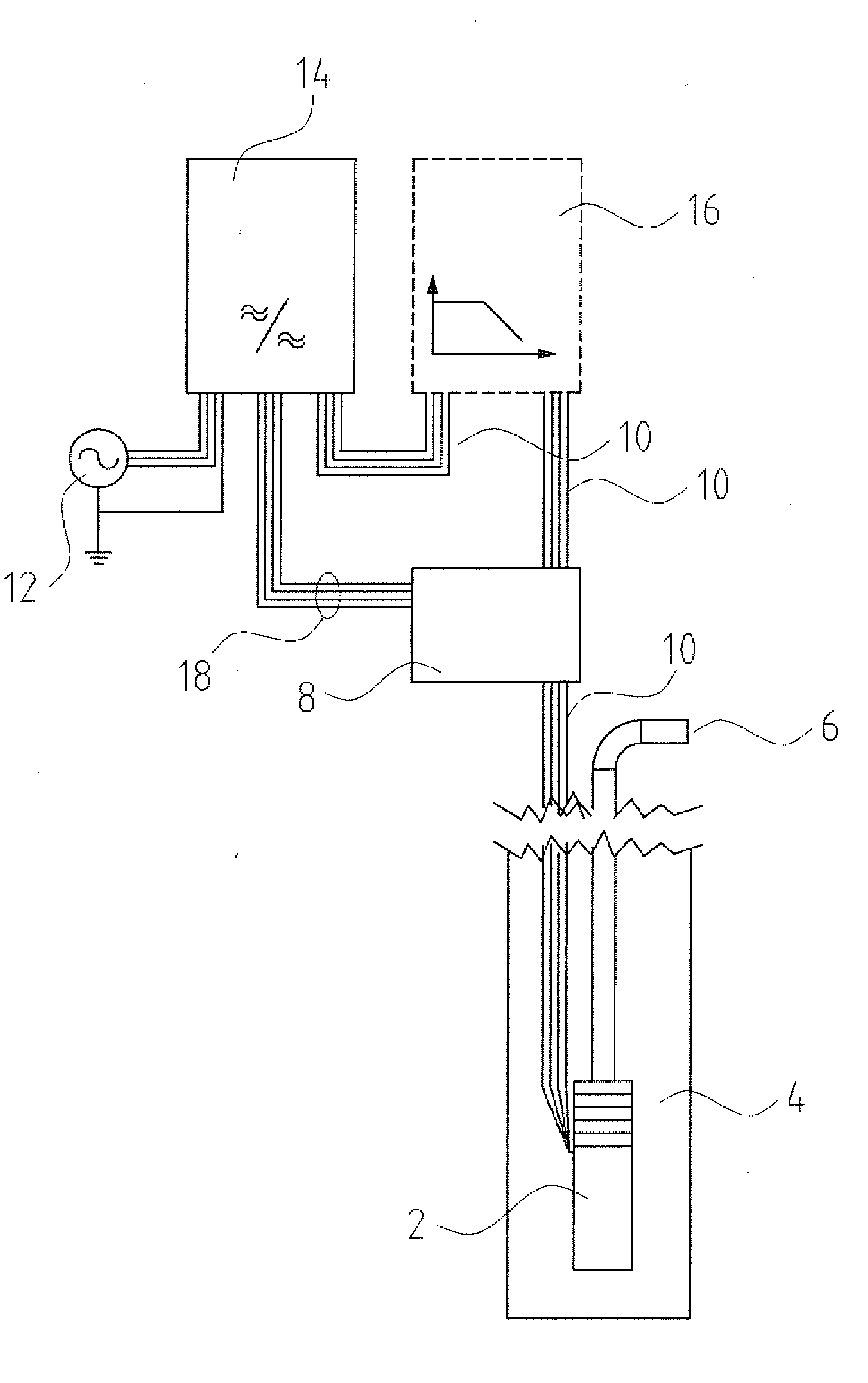
[0034]The overall construction of a pump system according to an embodiment of the invention is explained by way of FIG. 1. The pump system comprises a submersible pump 2, which is arranged in a pump sump 4 in a manner known per se. There, a pressure conduit 6 extends out of the pump sump 4 to the surface. Furthermore, the pump system comprises a control device 8 for controlling the pump assembly 2, which is likewise arranged outside the pump sump 4, i.e., spatially distanced from the pump assembly 2. Due to the spatially distanced arrangement of the control device 8 and the pump assembly 2, a data transmission between both is necessary, in order to be able to transmit condition data, which are acquired in the pump assembly 2, for example pressure, temperature, etc., to the control device 8. According to the invention, for this purpose, no separate data lead is provided for the data transmission between the pump assembly 2 and the control device 8 or, vice versa, from the control dev...


PUM


Abstract

A method for data transmission between a pump assembly (2) and a control device (8) is provided, wherein the pump assembly (2) for the energy supply is connected via at least one electrical supply lead (10) to a frequency converter (14). The data transmission is effected via the electrical supply lead (10), and an evaluation of a data transmission signal (34) received by the pump assembly (2) or the control device (8) is only effected in low-disturbance regions of a carrier signal (22) formed by a supply current. A pump system designed for carrying out this method is also provided.

Description

CROSS-REFERENCE TO RELATED APPLICATIONS[0001]This application is a Section 371 of International Application No. PCT / EP2006 / 006939, filed Jul. 15, 2006, which was published in the German language on Feb. 8, 2007, under International Publication No. WO 2007 / 014638 A1, the disclosure of which is incorporated herein by reference.BACKGROUND OF THE INVENTION[0002]The invention relates to a method for data transmission between a pump assembly and a control device, as well as to a correspondingly designed pump system with a pump assembly and a control device which is spatially separated from the assembly.[0003]In particular, submersible pump systems are often designed such that a pump assembly is provided, which is inserted into a drill hole or a pump sump, while the associated control device is arranged in a spatially distanced manner outside the drill hole or pump sump. A data transmission between the pump assembly and the control device is therefore necessary for control and monitoring.[...

Claims


Application Information

Patent Timeline
IPC IPC(8): G01V1/40
CPCH04B3/54H04B2203/5491H04B2203/5483H04B2203/5416F04D13/0686F04D13/0693
Inventor NYBO, PETER JUNGKLASJENSEN, JORGEN
Owner GRUNDFOS MANAGEMENT AS
Why Eureka
Try Eureka