Information terminal device

a technology of information terminal and antenna, which is applied in the direction of separate antenna unit combinations, wireless communication, transmission, etc., can solve the problems of deteriorating the portability difficult for one compact antenna to support such a wide frequency range, and affecting the aesthetic appearance of information terminal devices, so as to reduce the number of extension slots required when a new radio system is supported, prevent antenna damage, and avoid aesthetic effects

Inactive Publication Date: 2009-02-26
MURATA MFG CO LTD
View PDF76 Cites 5 Cited by
  • Summary
  • Abstract
  • Description
  • Claims
  • Application Information

AI Technical Summary

Benefits of technology

[0012]The information terminal device may preferably include an extension slot that is electrically connected to the antenna. A wireless communication card can be mounted in the extension slot, and wireless communication can be performed using the antenna. In this manner, the antenna does not protrude from the wireless communication card, and therefore, damage to the antenna can be reliably prevented, and the antenna does not deteriorate the aesthetic appearance of the information terminal device.
[0013]In addition, the wireless board may preferably include RF circuit units supporting a plurality of different radio systems. If the wireless board supports a plurality of radio systems, the number of extension slots required when a new radio system is supported can be reduced.
[0014]In addition, the wireless communication card may preferably utilize one of the RF circuit units of a radio system corresponding to the wireless board. Thus, the need for an RF circuit unit in the wireless communication card can be eliminated. Accordingly, the size of the wireless communication card can be further reduced.
[0015]In addition, the radio system corresponding to the wireless communication card may preferably be different from the radio system corresponding to the wireless board. In this manner, a new radio system that is not supported by the wireless board can be easily used.
[0016]According to a preferred embodiment of the present invention, since a compact and a wide band antenna is provided, a plurality of radio systems can preferably be used by simply inserting a wireless communication card without an antenna into an extension slot. In addition, since the wireless communication card does not need to include an antenna, the size of the card can be reduced, and therefore, the size of the information terminal device can be reduced. Furthermore, since the antenna does not protrude from the wireless communication card, the antenna is not likely to be damaged, and the antenna does not deteriorate the aesthetic appearance of the information terminal device.

Problems solved by technology

However, such information terminal devices only utilize some of the radio systems shown in FIG. 13.
This is when a large number of radio systems are utilized, the wireless frequencies used range from about 400 MHz to about 6 GHz, and therefore, it is difficult for one compact antenna to support such a wide frequency range.
However, if a large antenna is used, the size of information terminal devices becomes too large, thereby deteriorating their portability.
In addition, the antenna protruding from the wireless communication card is easily damaged, and the protruding antenna deteriorates the aesthetic appearance of the information terminal device.
However, even in such an information terminal device, if a new radio system is utilized, a wireless communication card with an antenna for the new radio system is required.
Thus, a problem similar to the problem of the device described in Japanese Unexamined Patent Application Publication No. 8-279027 arises.

Method used


Image

  • Information terminal device
  • Information terminal device
  • Information terminal device

Examples


Embodiment Construction

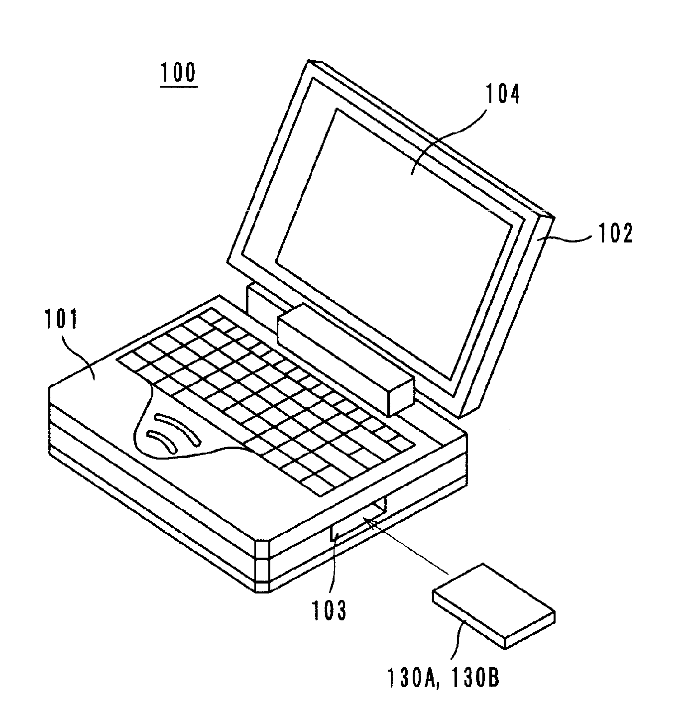
[0031]Preferred embodiments of an information terminal device according to the present invention are described below with reference to the accompanying drawings.

First Example of Antenna

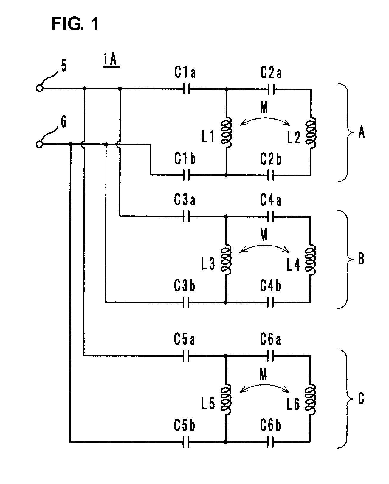
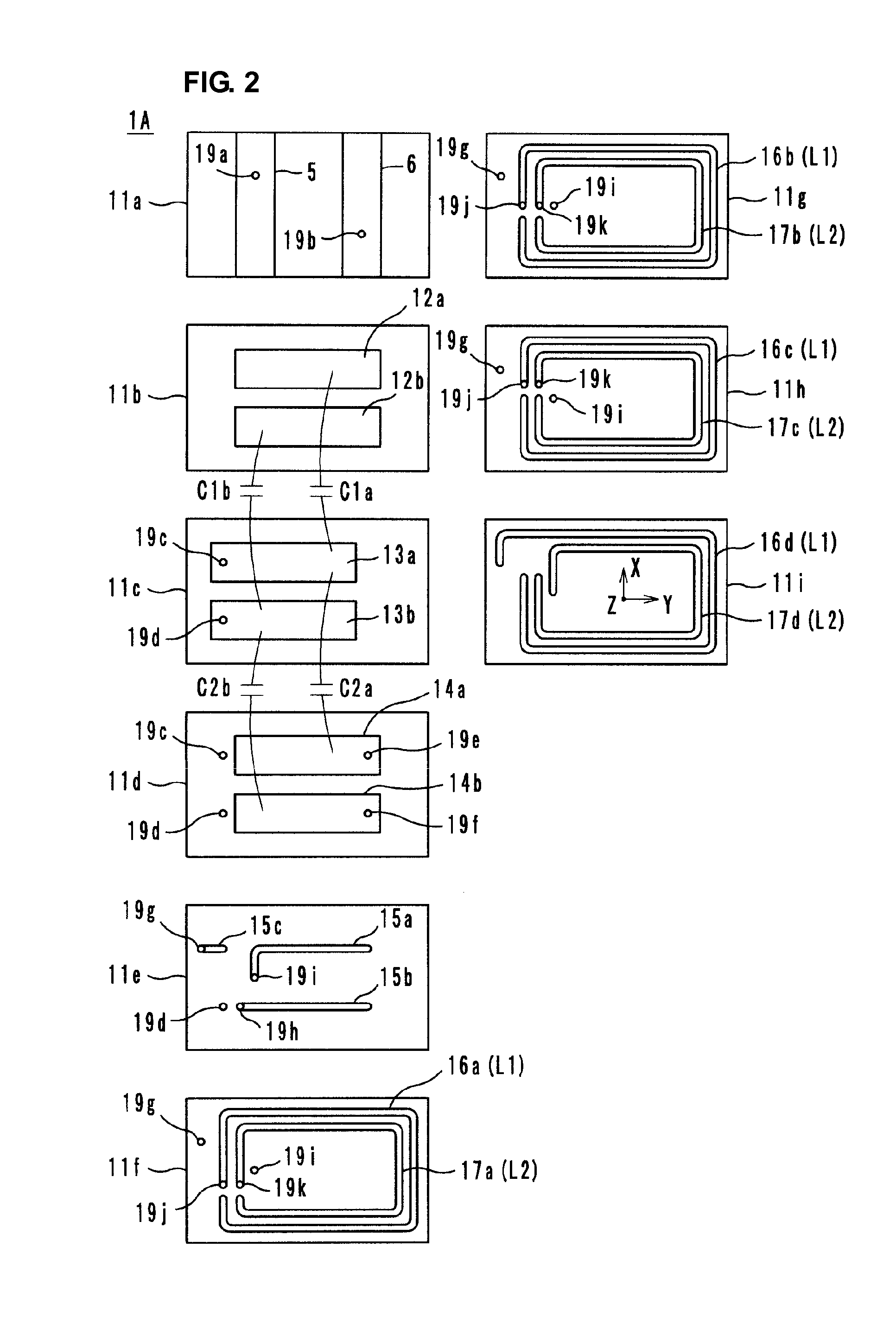
[0032]A first example of a compact wide-band antenna used for an information terminal device according to a preferred embodiment of the present invention is described first. As shown by an equivalent circuit in FIG. 1, an antenna 1A includes blocks A, B, and C, each including two LC series resonant circuits. The two LC series resonant circuits included in the block A include inductance elements L1 and L2 that are magnetically coupled (shown by a reference symbol M). The two LC series resonant circuits included in the block B include inductance elements L3 and L4 that are magnetically coupled (shown by a reference symbol M). The two LC series resonant circuits included in the block C include inductance elements L5 and L6 that are magnetically coupled (shown by a reference symbol M). The inductance elem...


PUM


Abstract

An information terminal device includes a casing, a wireless board, and an antenna arranged to utilize a plurality of radio systems. The antenna includes a power feeding terminal and a plurality of resonant circuits. The plurality of resonant circuits are arranged to radiate radio waves. The plurality of resonant circuits further define a matching circuit that provides impedance matching between an impedance on a power feeding side as viewed from the power feeding terminal and a radiation impedance of a free space.

Description

BACKGROUND OF THE INVENTION[0001]1. Field of the Invention[0002]The present invention relates to an information terminal device, such as a notebook personal computer, that utilizes a plurality of radio systems.[0003]2. Description of the Related Art[0004]In recent years, wireless services for mobile devices and motor vehicles have been increasingly provided. Examples of such services include Wideband-Code Division Multiple Access (W-CDMA), Global System for Mobile communications (GSM), a wireless Local Area Network (LAN), digital television broadcast, and Worldwide interoperability for Microwave Access (WiMAX). As shown in FIG. 13, frequencies in a wide band from about 400 MHz to greater than about 5 GHz are used for these services.[0005]Nowadays, information terminal devices that utilize a combination of a PHS and a wireless LAN, information terminal devices that utilize a combination of W-CDMA, GSM in three frequency bands, a wireless LAN, and DVB-H, and information terminal devic...

Claims


Application Information

Patent Timeline
Patent Type & Authority Applications(United States)
IPC IPC(8): H04W88/02
CPCH01Q1/2275H01Q7/00H04B1/38H04B1/0458H04B1/18H01Q21/30
Inventor KATO, NOBORUMANDAI, HARUFUMIKIMURA, IKUHEI
Owner MURATA MFG CO LTD
Why Eureka
Try Eureka