Signal processing device, signal processing method, and program therefor

Active Publication Date: 2009-02-26
SONY CORP
View PDF11 Cites 64 Cited by
  • Summary
  • Abstract
  • Description
  • Claims
  • Application Information

AI Technical Summary

Benefits of technology

[0017]In other words, as a result of the present invention, bass enhancement can be conducted wherein the disadvantages of the boost

Problems solved by technology

However, when the technique of boosting the bass signal is adopted from among the above, non-linear distortion becomes a problem.
More specifically, when the signal level input into the speaker exceeds a set tolerance value, bass fullness cannot be incr

Method used


Image

  • Signal processing device, signal processing method, and program therefor
  • Signal processing device, signal processing method, and program therefor
  • Signal processing device, signal processing method, and program therefor

Examples


first embodiment

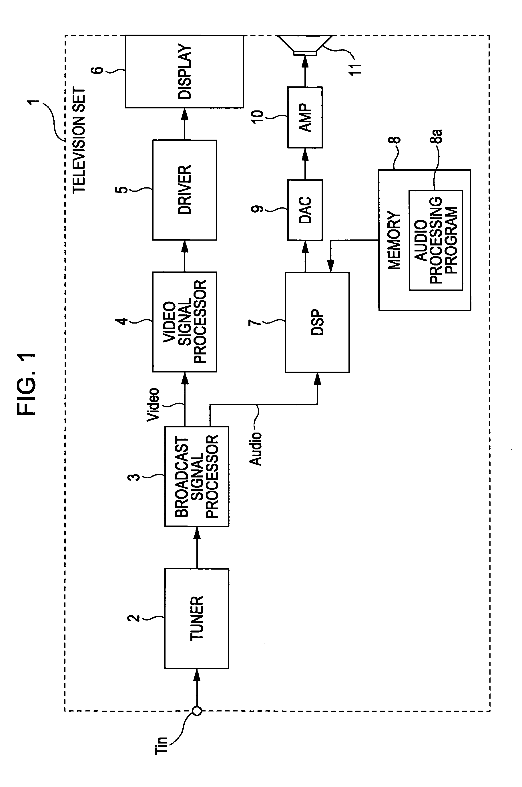
[0044]FIG. 1 is a block diagram illustrating the internal configuration of a television set 1, which acts as the signal processing device according to the first embodiment of the present invention.

[0045]The television set 1 receives digital television broadcasts, and according to the received signal, conducts image display and audio playback. First, a broadcast signal from a digital television broadcast is received using an antenna (not shown in the drawings), and then input into the television set 1 from the terminal Tin shown in the figure.

[0046]The received signal from the antenna is then input into a tuner 2 via the terminal Tin. The tuner 2 is configured to receive a carrier (i.e., a receiver frequency signal) that has been specified by a channel selection operation or similar means. The tuner 2 then performs Viterbi decoding and error correction processing, for example, and thereby obtains a TS (Transport Stream).

[0047]As is commonly known, a TS is defined by digital broadcast...

second embodiment

[0132]A second embodiment will now be described.

[0133]FIG. 14 is a diagram for explaining the configuration of a signal processing device in accordance with the second embodiment of the present invention. In the second embodiment, operations related to the audio signal processing of the first embodiment described in the foregoing are realized by the processing operations of a CPU (Central Processing Unit).

[0134]FIG. 14 illustrates the internal configuration of electronic equipment having a signal processing device provided by such a CPU. This electronic equipment is assumed to be a personal computer, for example.

[0135]As shown in FIG. 14, first an audio signal (digital audio signal) is played back from a recording medium (not shown in the drawings) and supplied to a CPU 25.

[0136]The CPU 25 is provided with memory 26, the CPU 25 being able to read data therefrom and write data thereto. The memory 26 is used by the CPU 25 as a work area, while also storing information such as paramete...

third embodiment

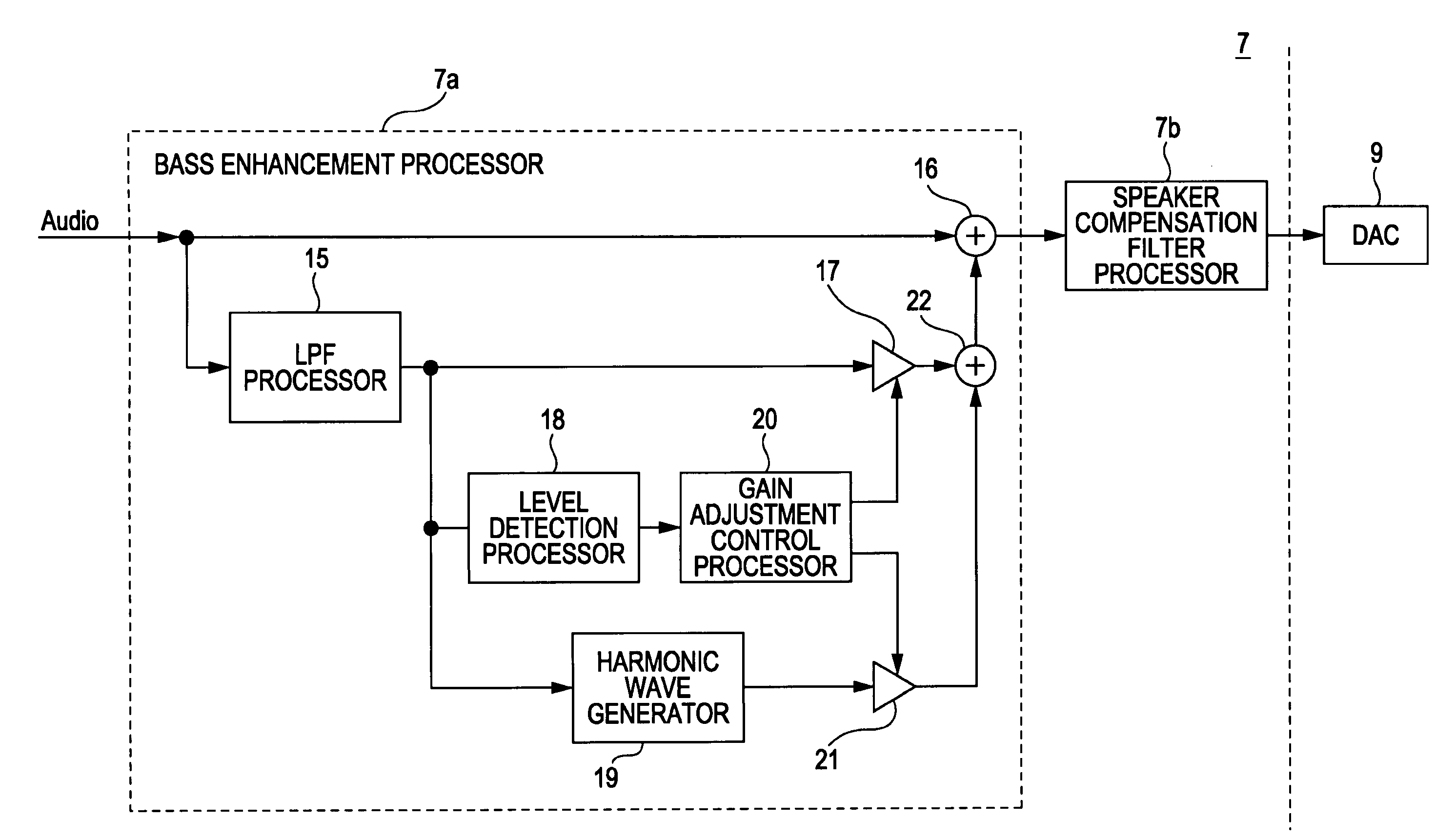
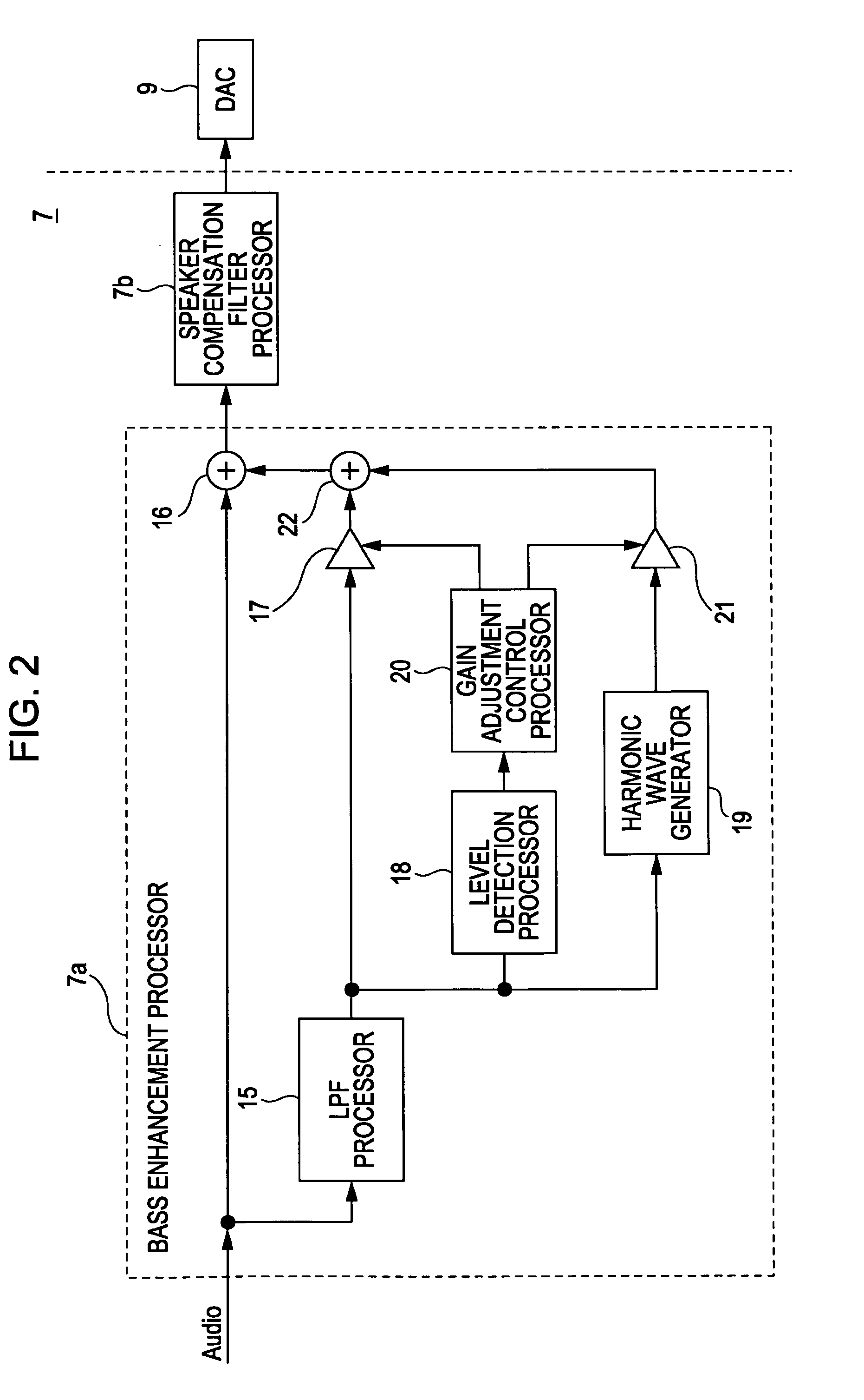
[0146]FIG. 16 is a diagram for explaining the configuration of a television set in accordance with the third embodiment of the present invention. The configuration of the television set in accordance with the third embodiment is identical to that of the television set 1 in accordance with the first embodiment, being different only in that the processing conducted by the DSP 7 differs. For this reason, FIG. 16 primarily illustrates only the functional processing blocks realized by the DSP 7 in this case (the DAC 9 external to the DSP 7 in this case is also shown).

[0147]Furthermore, it should be appreciated that in the television set in accordance with the third embodiment, the content of the audio processing program 8a stored in the memory 8 has been modified such that digital signal processing for realizing each processing function shown in FIG. 16 is executed by the DSP 7.

[0148]Since some functional processing blocks shown in FIG. 16 have already been described with reference to FI...


PUM


Abstract

A signal processing device includes a bass signal extractor, a harmonic wave generator, a level detector, and an adjustment controller. The bass signal extractor first extracts a bass signal from an input audio signal. Natural-sounding bass enhancement is achieved as a result of the adjustment controller boosting the bass signal level until the level detector detects the bass signal level at a set level. For input bass signal levels higher than the set level, bass is enhanced virtually using a harmonic signal generated from the bass signal by the harmonic wave generator. As a result, the disadvantages of the boost method and the virtual signal enhancement method are mutually compensated for, and synergistic advantages for bass enhancement are obtained.

Description

CROSS REFERENCES TO RELATED APPLICATIONS[0001]The present invention contains subject matter related to Japanese Patent Application JP 2007-216983 filed in the Japanese Patent Office on Aug. 23, 2007, the entire contents of which are incorporated herein by reference.BACKGROUND OF THE INVENTION[0002]1. Field of the Invention[0003]The present invention relates to a signal processing device that processes an input audio signal, as well as a method and program therefor.[0004]2. Description of the Related Art[0005]When conducting sound reproduction using a speaker on the basis of an audio signal, it is known that in sound reproduction using a small speaker, for example, ample bass reproduction cannot be realized due to limitations imposed by the physical volume of the speaker.[0006]FIG. 25 shows a comparison between the frequency characteristics (i.e., frequency-amplitude characteristics) of a large speaker and a small speaker. In the case of the large speaker indicated in FIG. 25A, ampli...

Claims


Application Information

Patent Timeline
IPC IPC(8): H03G5/00
CPCH03G9/025H04R3/04
Inventor YAMADA, YUJIOKIMOTO, KOYURU
Owner SONY CORP
Why Eureka
Try Eureka