Dual End Gear Fluid Drive Starter

a fluid drive and dual-end gear technology, applied in the direction of fluid couplings, gearing, lighting and heating apparatus, etc., can solve the problems of extra facility hardware, time-consuming effort, additional starting power, etc., and achieve the effect of increasing the rotation speed of the cstc output sha

Inactive Publication Date: 2009-02-26
EXXONMOBIL UPSTREAM RES CO
View PDF68 Cites 21 Cited by
  • Summary
  • Abstract
  • Description
  • Claims
  • Application Information

AI Technical Summary

Benefits of technology

[0014]In a second embodiment of an apparatus of the present invention a dual end gear compressor starting torque converter (CSTC) for use in a string of rotating machines is provided. The dual end gear CSTC comprises a CSTC; an input end and an output end; a lock-up mechanism for mechanically connecting the CSTC input end to the CSTC output end at synchronous speed (which allows the drive end and the driven end of the CSTC to mechanically engage and enable rigid rotation between the prime mover and the load(s) at synchronized speed) between the input end and the output end; a speed reducing gear train at the input end; and a speed increasing gear train at the output end. A housing may surround and enclose the entire dual end gear CSTC assembly, or separate housings may be utilized. The speed increasing gear train and speed reducing gear train may each be of single helix construction, or may each be of double helix construction.
[0015]In a third embodiment of an apparatus of the present invention a rotating equipment power string for use in process refrigeration service (e.g. compressing natural gas to form liquefied natural gas (LNG)) including a compressor starting torque converter (CSTC) is provided. The rotating equipment power string comprising a single shaft gas turbine having an input shaft and an output shaft; at least one process refrigeration compressor with an input shaft and a nominal speed requirement; a starter motor operatively connected to said turbine input shaft; and a CSTC and gearing assembly for delivering power from said single shaft gas turbine to said at least one process refrigeration compressor. The CSTC and gearing assembly comprising a CSTC having a constant speed input shaft to a hydraulic pump; said hydraulic pump supplying hydraulic fluid to a hydraulic turbine through adjustable guide vanes; said hydraulic turbine being connected to a CSTC output shaft such that the speed of the output shaft increases from zero to full speed by adjusting said guide vanes; said CSTC further comprising a lock-up mechanism for mechanically connecting said CSTC input shaft to said CSTC output shaft at synchronous speed. The apparatus further includes a speed reducing gear train including a speed reducing gear train input shaft connected to a high speed gear, said high speed gear mechanically meshed to a low speed gear carried by a speed reducing gear train output shaft, wherein said speed reducing gear train output shaft is connected to said CSTC input shaft; and a speed increasing gear train including a speed increasing gear train input shaft, wherein said speed increasing gear train input shaft is connected to said CSTC output shaft, a low speed gear connected to said speed increasing gear train input shaft, and a high speed gear mechanically meshed to said low speed gear, wherein said high speed gear is connected to a speed increasing gear train output shaft that is connected to said process refrigeration compressor input shaft.
[0016]In a fourth embodiment of the present invention, a method of starting at least one compressor in a string of rotating power equipment is provided. The method comprising providing a string of rotating power equipment including a prime mover; connecting a speed reducing gear train to said prime mover; connecting a compressor starting torque converter (CSTC) to said speed reducing gear train; connecting a speed increasing gear train to said CSTC; connecting at least one compressor to said speed increasing gear train; starting said prime mover to produce power at a first output speed; reducing said first speed to a second speed lower than said first speed by said speed reducing gear train; transmitting power increasingly through said CSTC at output speeds from zero to said second lower than said first speed; increasing said second speed to a third speed higher than said second speed by said speed increasing gear train; and driving said compressor at said third speed. The pressurized start preferably starts up at minimum startup power and transitions to full power when the speed increasing gear train reaches the said third speed.
[0017]In a fifth embodiment of the present invention, a method of manufacturing LNG using a string of rotating power equipment is provided. The string of rotating power equipment comprises a prime mover having an output shaft; a speed reducing gear train connected to said prime mover, said speed reducing gear train having an output shaft and an input shaft, said speed reducing gear train output shaft rotating at a lower speed than said prime mover output shaft; a compressor starting torque converter (CSTC) connected to said speed reducing gear train output shaft, wherein the CSTC includes an output shaft and a lock-up mechanism for mechanically connecting the compressor starting torque converter input shaft to the compressor starting torque converter output shaft at synchronous speed; a speed increasing gear train connected to said CSTC output shaft and having a speed increasing gear train output shaft rotating at a higher speed than said CSTC output shaft; and a driven load connected to said speed increasing gear train output shaft, wherein the rotation speed of said CSTC output shaft can be increased by said speed increasing gear train to meet the operating speed requirement of said driven load. The prime mover may be a single shaft turbine or a motor.
[0018]In a sixth embodiment of the present invention, a method of manufacturing LNG utilizing a dual end gear compressor starting torque converter (CSTC) in a string of rotating machines is provided. The dual end gear CSTC comprises a compressor starting torque converter (CSTC); an input end and an output end; a lock-up mechanism for mechanically connecting the CSTC input end to the CSTC output end at synchronous speed between the input end and the output end; a speed reducing gear train at the input end; and a speed increasing gear train at the output end.
[0019]In a seventh embodiment of the present invention, a method for manufacturing LNG is provided. The method comprises providing natural gas and providing a string of rotating power equipment. The string of rotating power equipment comprising a prime mover having an output shaft, a speed reducing gear train connected to said prime mover, said speed reducing gear train having an output shaft and an input shaft, said speed reducing gear train output shaft rotating at a lower speed than said prime mover output shaft; a compressor starting torque converter (CSTC) connected to said speed reducing gear train output shaft, wherein the CSTC includes an output shaft; a speed increasing gear train connected to said CSTC output shaft and having a speed increasing gear train output shaft rotating at a higher speed than said CSTC output shaft; and a compressor connected to said speed increasing gear train output shaft, wherein the rotation speed of said CSTC output shaft can be increased by said speed increasing gear train to meet the operating speed requirement of said compressor. The method further comprises feeding a refrigerant to said compressor; compressing said refrigerant in said compressor, thereby forming a compressed refrigerant; expanding said compressed refrigerant to form a cooled refrigerant; cooling said natural gas by indirect heat exchange with said cooled refrigerant; and recovering LNG.

Problems solved by technology

Gas make-up may require extra facility hardware (valves, piping, transmitters, flares, gas reclamation, and associated controls) and is a time consuming effort.
A pressurized start removes necessary hardware associated with the gas make-up of depressurized start; however, it requires additional starting power due to a higher starting torque necessitated by gas in the compressor causing a higher internal compressor load.
However, a VFD is a large capital expense and may contribute up to 70% of the cost in a motor / VFD package.
The CSTC of Schmidt is coupled to a gas turbine and a compressor, but is incapable of starting up a compressor string of over 50,000 horsepower (hp) (less than 40 megawatts (MW)).
Power to speed performance of the CSTC is limited.
In a depressurized start, where the loads in a compressor string are reduced, a CSTC may be capable of performing a start; however, CSTC technology alone is power-limited in starting high load compressor strings such as pressurized starts in high-load compressor strings.
Given the high speed requirement of current high power compressors, the CSTC is not capable of outputs at the necessary speed and power.

Method used


Image

  • Dual End Gear Fluid Drive Starter
  • Dual End Gear Fluid Drive Starter
  • Dual End Gear Fluid Drive Starter

Examples


Embodiment Construction

[0029]In the following detailed description section, the specific embodiments of the present invention are described in connection with preferred embodiments. However, to the extent that the following description is specific to a particular embodiment or a particular use of the present invention, this is intended to be for exemplary purposes only and simply provides a description of the exemplary embodiments. Accordingly, the invention is not limited to the specific embodiments described below, but rather, it includes all alternatives, modifications, and equivalents falling within the true spirit and scope of the appended claims.

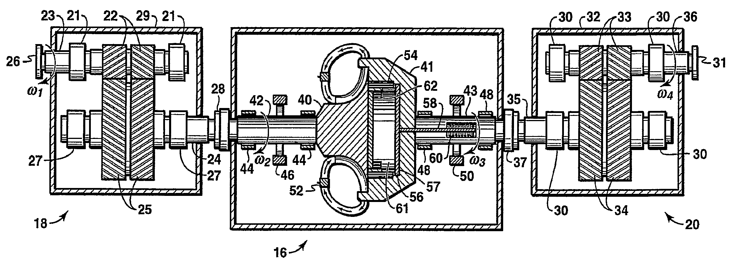
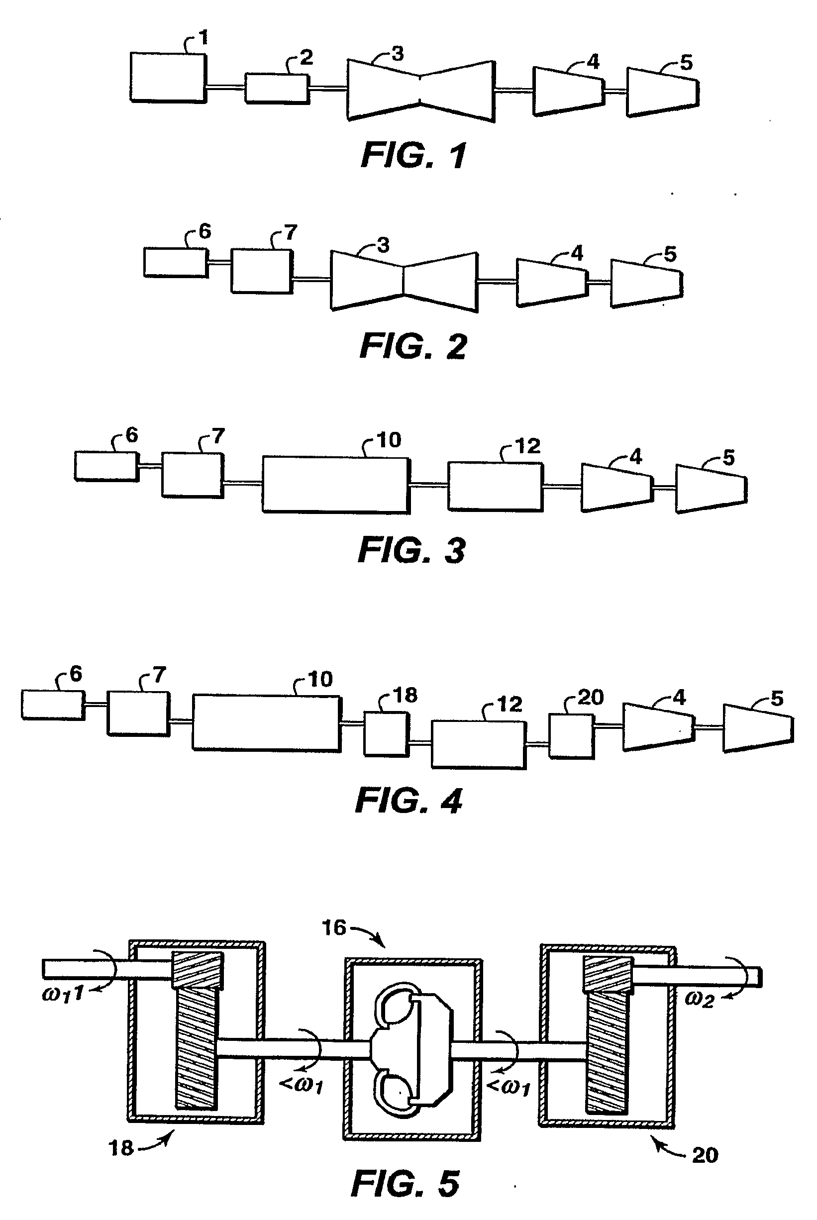
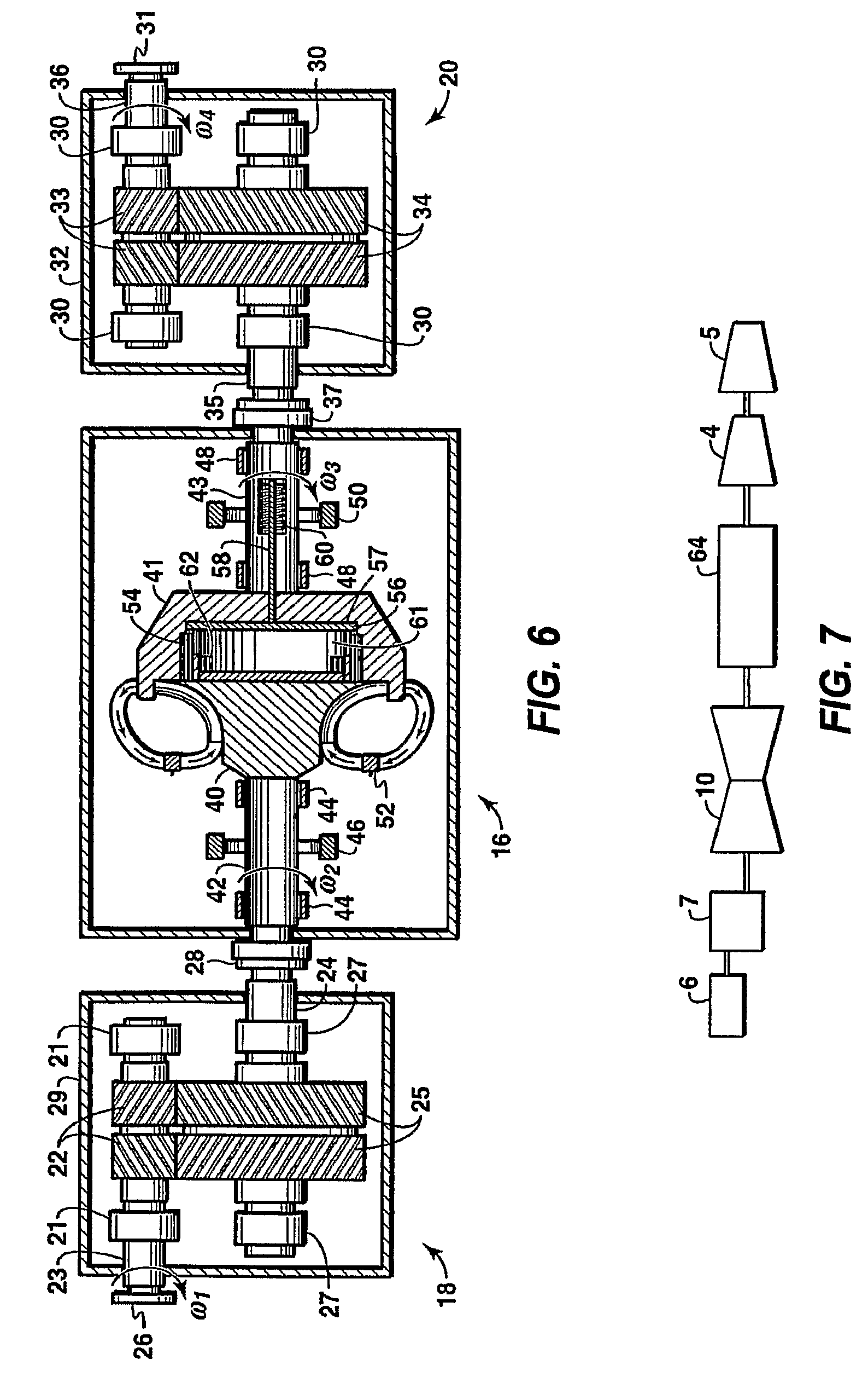
[0030]Some embodiments of the present invention relate to a mechanical technique to start a string. Starting a string may be achieved by one of two primary conditions. The first condition is depressurized start, and the second is pressurized start. A pressurized start (e.g. at settle out pressure) removes necessary hardware associated with the depressurized ...


PUM


Abstract

A compressor starting torque converter method and apparatus for high power rotating equipment strings includes a compressor starting torque converter (CSTC) (16) and gearing to make the input and output speed conform to the speed and power requirements of the at least one compressor (4) at the end of the string. The string also includes a prime mover (10), either a motor or gas turbine with a starter motor. The CSTC is driven by a prime mover that has been geared down (via 18) to an appropriate speed for efficient power transfer, followed by a gear increasing unit (20) to allow the output of the CSTC to be increased to conform to the necessary requirements of a high speed compressor. The gearing can be two separate units with their own housings, or incorporated in a single housing with the CSTC. The CSTC may be a CSTC used in pressurized starts high compressor load strings for LNG refrigeration service.

Description

CROSS REFERENCE TO RELATED APPLICATIONS[0001]This application claims the benefit of U.S. Provisional Application No. 60 / 779,680, filed 6 Mar. 2006.[0002]This application is related to U.S. Provisional No. 60 / 753,717, entitled Multi-Compressor String With Multiple Variable Speed Fluid Drives, filed Dec. 23, 2005 by Christopher G. Holt and William L. Martin. U.S. Provisional No. 60 / 753,717 was subsequently filed as International Application No. PCT / US2006 / 043287 on 8 Nov. 2006.BACKGROUND OF THE INVENTION[0003]This section is intended to introduce various aspects of the art, which may be associated with exemplary embodiments of the present invention. This discussion is believed to assist in providing a framework to facilitate a better understanding of particular aspects of the present invention. Accordingly, it should be understood that this section should be read in this light, and not necessarily as admissions of prior art.[0004]The present invention generally concerns a method for s...

Claims


Application Information

Patent Timeline
Patent Type & Authority Applications(United States)
IPC IPC(8): F16H47/06F16D33/00F25J1/00
CPCF04D25/022F16H47/06F25J1/0283F25J1/0284Y10T74/19023F25J1/0298F25J2230/20F25J2280/10F25J1/0287
Inventor HOLT, CHRISTOPHER G.MARTIN, WILLIAM L.
Owner EXXONMOBIL UPSTREAM RES CO
Why Eureka
Try Eureka