Perfusion circuit and use therein in targeted delivery of macromolecules

a micromolecule and perfusion circuit technology, applied in the field of perfusion circuits, can solve the problems of heart failure and applicability of gene therapy, and achieve the effects of maximizing safety, minimizing the priming volume of the circuit, and efficient myocyte gene delivery

a micromolecule and perfusion circuit technology, applied in the field of perfusion circuits, can solve the problems of heart failure and applicability of gene therapy, and achieve the effects of maximizing safety, minimizing the priming volume of the circuit, and efficient myocyte gene delivery

US20090054823A1Inactive Publication Date: 2009-02-26THE TRUSTEES OF THE UNIV OF PENNSYLVANIA

Image

  • Perfusion circuit and use therein in targeted delivery of macromolecules
  • Perfusion circuit and use therein in targeted delivery of macromolecules
  • Perfusion circuit and use therein in targeted delivery of macromolecules

Examples


examples

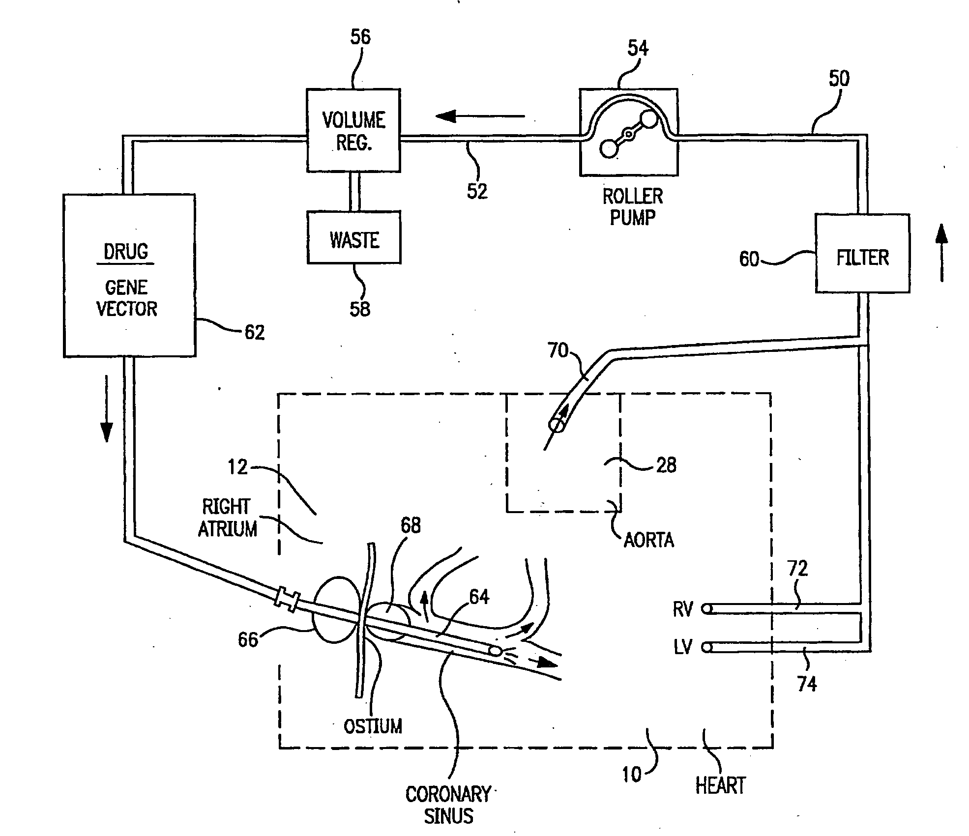
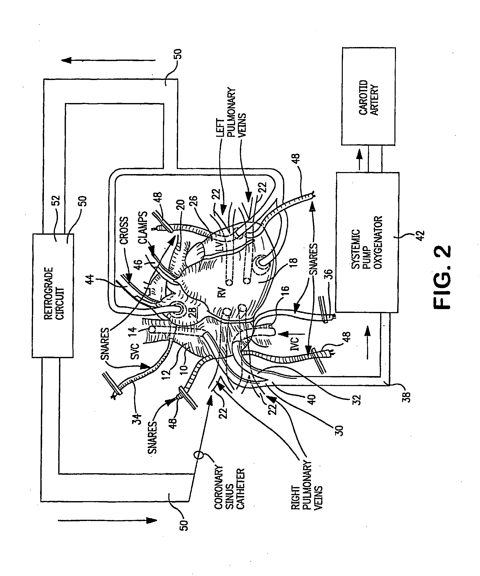
[0079]In the following experiments, the inventors compare, using quantitative and histochemical methods, the relative transduction efficiency of a novel method and system of the invention (using cardiopulmonary by-pass, two-way cardiac isolation and retrograde infusion) in the experimental group of animals to a control group in which an equal titer of vector and equal dose of endothelial permeabilizing agent are administered retrograde directly via a catheter in the coronary sinus. Although these studies use an open-chest approach, the control group is designed to simulate what could be achieved using a percutaneous catheter-based transvascular vector delivery technique in a large adult mammal.

[0080]The following experiments are illustrative of the method of the invention, but do not limit the invention.

Methods:

[0081]Both the two experimental groups, (n=6, cardiopulmonary by-pass, “CPB”) and (n=1, “PILOT AAV”); and the control group, (n=3, “CATHETER”) consist of normal male canines,...


PUM


Abstract

A perfusion circuit and a use thereof for delivering a substance to a subject's heart in situ during cardiopulmonary bypass surgery are provided. The perfusion circuit defines a path for re-circulating a solution containing a macromolecular complex through a coronary circulation circuit (50) through a subject's heart during a surgical procedure in which the substance is prevented from being delivered to the subject's other organs.

Description

STATEMENT REGARDING FEDERALLY SPONSORED RESEARCH OR DEVELOPMENT[0001]This application contains work supported by grants from the National Institutes of Health (NIH), NIBIB 1-R21-EB003223-01 and NIBIB 5-R21-EB003223-02. The US government may have certain rights in this invention.BACKGROUND OF THE INVENTION[0002]The present invention relates to a perfusion circuit for use in delivering substances, such as macromolecular complexes, including small molecules, gene therapy vectors, or the like to the heart.[0003]Cardiovascular disease is a leading cause of death in the United States, and heart is failure is a major public health problem in the United States. Gene therapy may provide promising new therapies for this vexing public health problem. However, gene delivery is the most important as yet unsolved problem limiting the applicability of gene therapy for the treatment of heart failure. This applies equally to heart failure due to defined X-linked or autosomal recessive gene defects a...

Claims


Application Information

Patent Timeline
26 Feb 2009
Publication
US20090054823A1
IPC
A61M1/16
CPC
A61M1/3621; A61M25/1002; A61M1/3659; A61M1/3613; A61M25/1011; A61M1/3603
Inventors
BRIDGES, CHARLES R.; STEDMAN, HANSELL H.