Monolithic Mirror Array

a mirror array and monolithic technology, applied in the direction of heat collector mounting/support, instruments, lighting and heating equipment, etc., can solve the problems of the manufacture cost itself, and achieve the effects of reducing production costs, high melting temperature, and improving solar energy

Inactive Publication Date: 2009-03-05
SOLFOCUS
View PDF23 Cites 57 Cited by
  • Summary
  • Abstract
  • Description
  • Claims
  • Application Information

AI Technical Summary

Benefits of technology

[0004]The invention provides a solid optical component with integral alignment or attachment features formed from a single piece of formable material. The solid optical component may be used as a primary mirror in a concentrated solar energy unit. The present invention also provides a monolithic mirror array of multiple optical components. The optical components of this invention provide for an improved solar energy device by reducing production cost and offering lightweight material options. In accordance with this invention the monolithic array may be made from a single piece of formable material and have a plurality of concave, substantially parabolic mirror surfaces and a plurality of openings at the bases of the concave mirror surfaces. The material may also possess a high melting temperature and a thermal stability that enables the optical components to function at temperatures between about −40 and +200° C. Alignment or attachment features that are integral with the optical components enable high-precision connections between the optical components and a supporting structure, such as a backpan or other optical components. Monolithic arrays of optical components may be formed from a single sheet of a formable material using a thermal forming or an injection molding process. The shape of the monolithic array may be supplemented by stiffening features formed from the single sheet of plastic, fiberglass, metal or glass. The invention provides an array of optical components to be monolithically fabricated as primary mirrors for a solar concentrator array.

Problems solved by technology

Manufacturing cost itself is affected by other aspects, such as material costs, the number of components required for assembly, manufacturing tolerances, and processing efficiencies.

Method used


Image

  • Monolithic Mirror Array
  • Monolithic Mirror Array
  • Monolithic Mirror Array

Examples


Embodiment Construction

[0010]Reference now will be made in detail to embodiments of the disclosed invention, one or more examples of which are illustrated in the accompanying drawings.

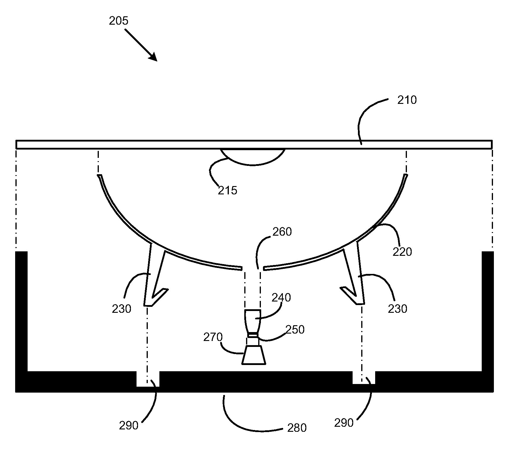
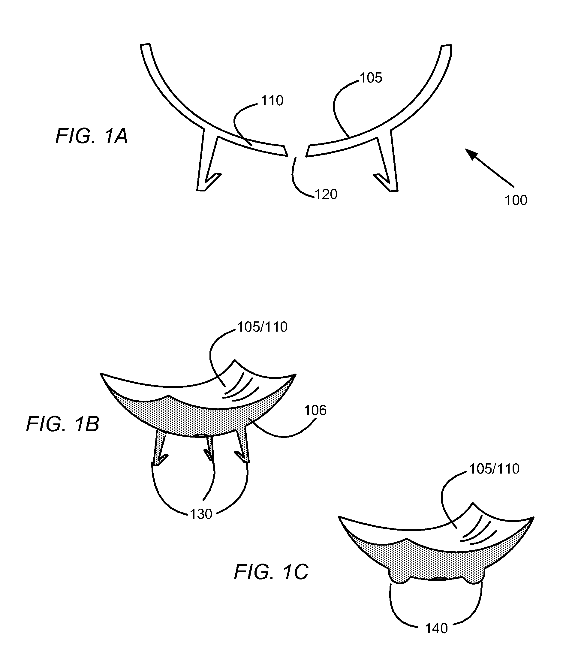
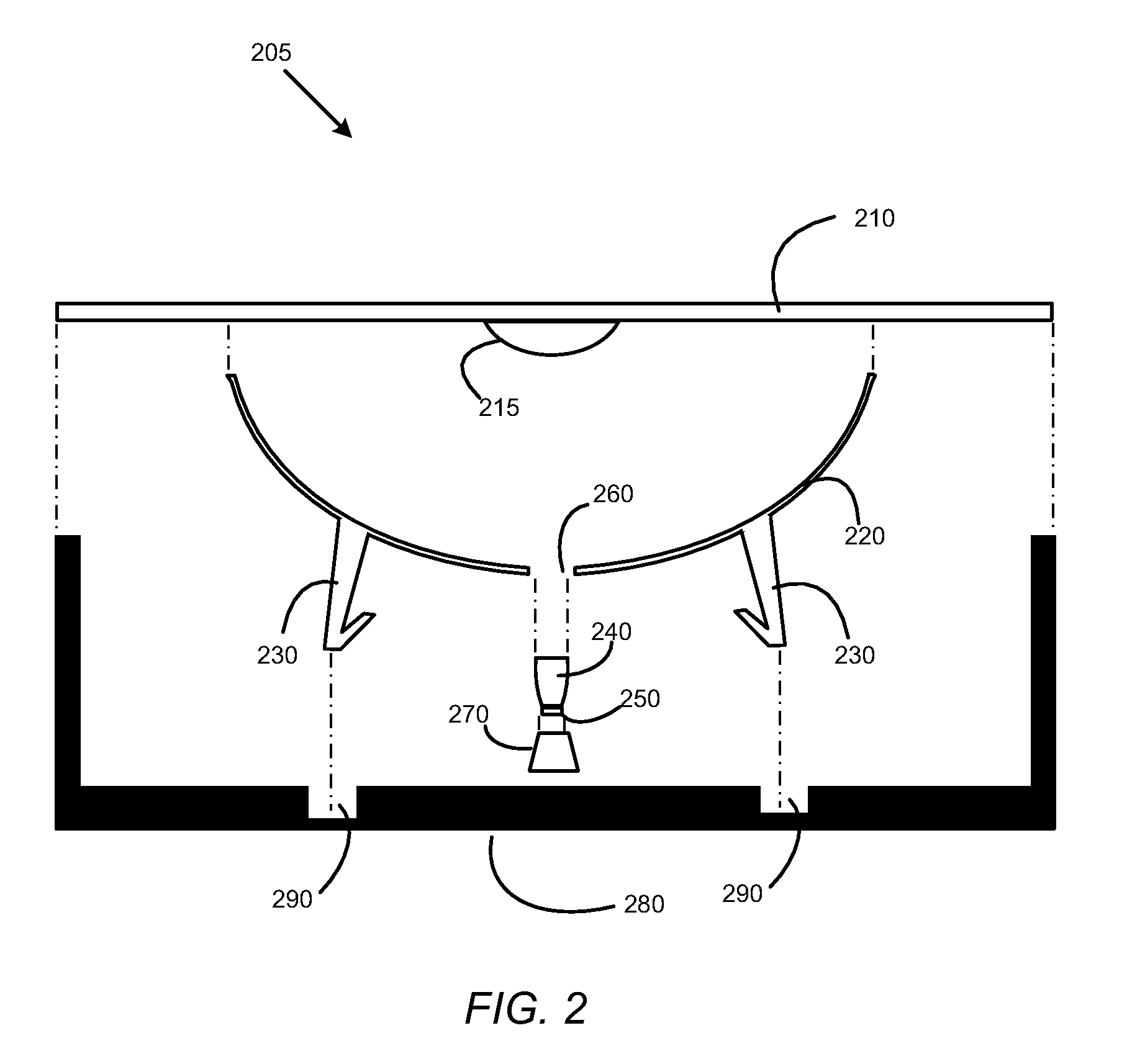
[0011]FIG. 1A illustrates a solid optical component 100 according an embodiment of this invention. The optical component 100 includes a curved solid body 110, a reflective concave mirror surface 105 and an aperture 120 at the base of the curved body 110. In one embodiment, the concave surface 105 may be substantially parabolic in shape. The optical component 100 may be made of any formable material that maintains shape and stiffness over a broad range of temperatures. For solar applications, the material is chosen to be stable at the typical working temperatures of a concentrated solar energy system. In one embodiment, the formable material may have high thermal stability over a working temperature range from about −20 to about +150° C. In another embodiment the solid optical component may withstand a working temperature ran...


PUM


Abstract

The present invention is an improved solar concentrator array utilizing a monolithic array of primary mirrors fabricated from a single sheet of formable material. The material may include glass, plastic, and metal of a high thermal stability to be able to withstand a broad range of temperature conditions. The monolithic array of this invention may include integral alignment or attachment features for attachment to a supporting structure.

Description

RELATED APPLICATIONS[0001]This application is a continuation-in-part of the following: (1) U.S. Non-Provisional patent application Ser. No. 11 / 138,666 filed on May 26, 2005 entitled “Concentrator Solar Photovoltaic Array with Compact Tailored Imaging Power Units”; and (2) U.S. Provisional Patent Application Ser. No. 60 / 985,215 filed on Nov. 3, 2007 entitled “Monolithic Mirror Array”, all of which are hereby incorporated by reference as if set forth in full in this application for all purposes.BACKGROUND OF THE INVENTION[0002]Solar energy generation is an important and growing area in the field of environmentally friendly energy production. Solar concentrators are solar energy generators which increase the efficiency of converting solar energy into electricity. Solar concentrators utilize mirrors and lenses to concentrate light from a relatively large area onto a small photovoltaic cell. For example, the solar cell size in a solar concentrator may be less than 1% of the entry window ...

Claims


Application Information

Patent Timeline
Patent Type & Authority Applications(United States)
IPC IPC(8): H01L31/042G02B27/10
CPCF24J2/06H01L31/0547F24J2/12F24J2/18F24J2002/1071F24J2002/108F24J2002/4665F24J2002/5275G02B5/09Y02E10/42Y02E10/44Y02E10/52G02B19/0042G02B19/0023F24J2/1057F24S23/71F24S23/00F24S23/79F24S2025/011F24S2023/872F24S2023/86F24S23/82F24S2025/6004F24S50/20Y02E10/40
Inventor TIAN, JINGYOUNG, PETERELLSWORTH, JASONHORNE, STEPHEN J.FIRESTONE, STUART M.
Owner SOLFOCUS
Why Eureka
Try Eureka