Hydraulic power transmission with lock-up clutch

a technology of hydraulic power transmission and lock-up clutch, which is applied in the direction of rotary clutches, fluid couplings, gearing, etc., can solve the problems of inability to improve the fuel economy of the vehicle, the acceleration performance cannot be improved, and the vehicle is difficult to start moving smoothly, so as to achieve smooth rotation

Inactive Publication Date: 2009-03-05
AISIN AW CO LTD
View PDF11 Cites 9 Cited by
  • Summary
  • Abstract
  • Description
  • Claims
  • Application Information

AI Technical Summary

Benefits of technology

[0028]Furthermore, a damper is further added to the lock-up clutch of the hydraulic power transmission with a lock-up clutch according to the fourth aspect of the present invention, and the lock-up clutch and the damper serve as a path that changes the power transmission path of the fluid coupling. Ther

Problems solved by technology

However, even if, hypothetically, it is possible to improve the fuel economy, in the case in which a hydraulic power transmission, that has the characteristics described above, is combined with a small displacement engine, in which the maximum engine torque is generated at a high rotational speed, there is a possibility that the acceleration performance cannot be improved because the maximum engine torque is not generated immediately after the automobile starts to move.
In particular, when

Method used


Image

  • Hydraulic power transmission with lock-up clutch
  • Hydraulic power transmission with lock-up clutch
  • Hydraulic power transmission with lock-up clutch

Examples


Embodiment Construction

[0042]Hereinafter, exemplary embodiments of the present invention will be explained with reference to the drawings. Note that, in the exemplary embodiments, identical reference symbols and identical reference numerals denote identical or corresponding functional components, and thus, redundant explanations will be omitted here.

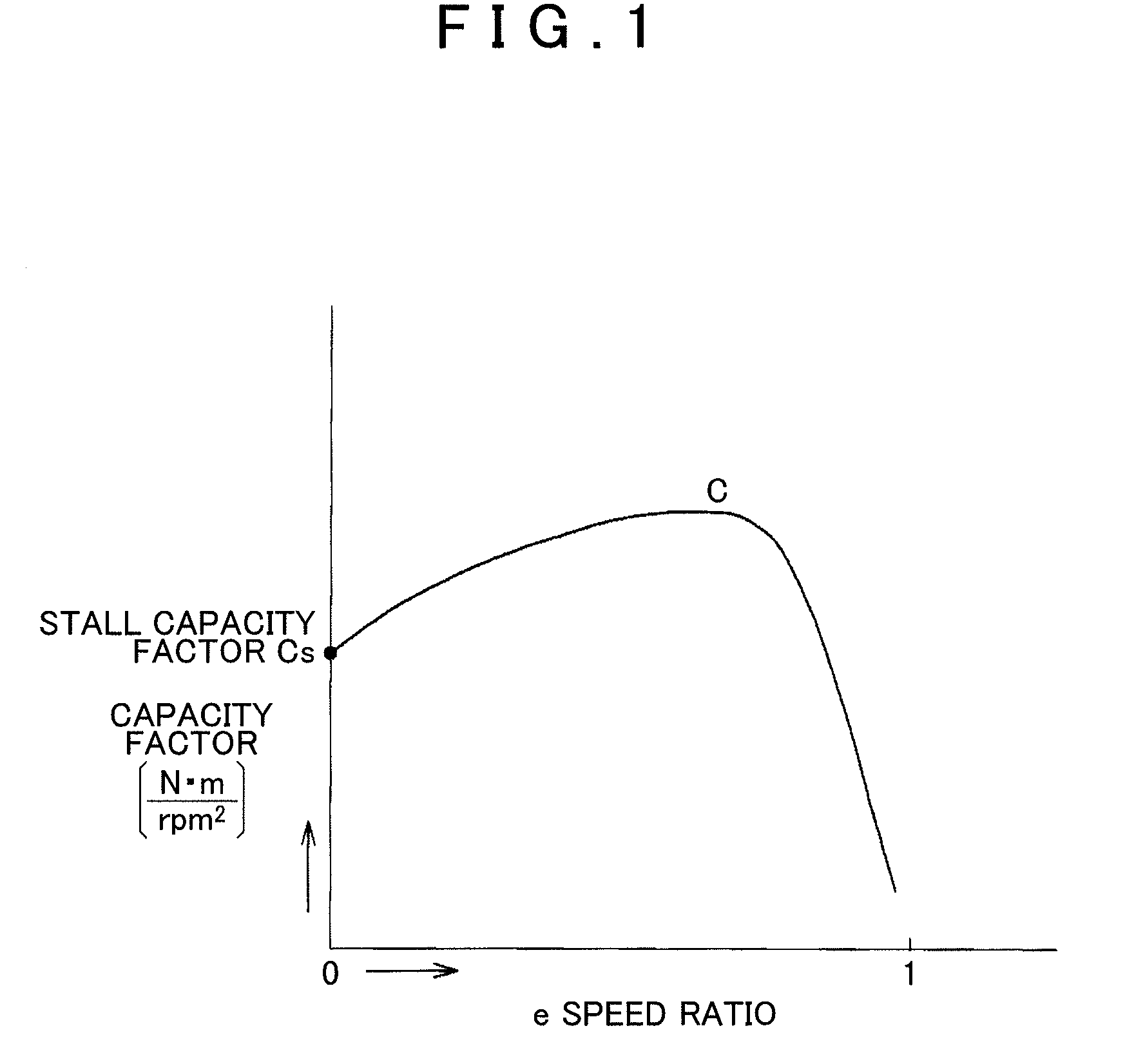
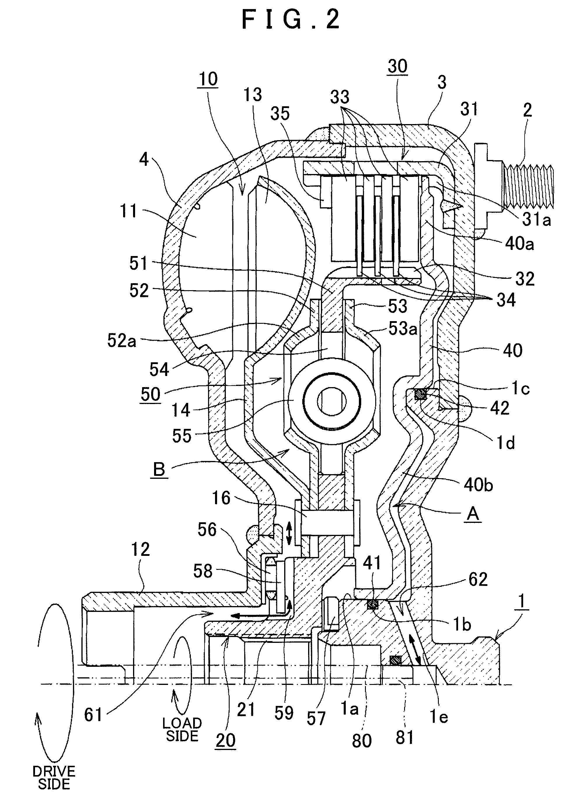
[0043]FIG. 2 is a drawing of a longitudinal section that shows the hydraulic power transmission with a lock-up clutch of an exemplary embodiment of the present invention. FIG. 3 is a characteristic diagram that shows a comparison of the characteristic diagrams of the hydraulic power transmission with a lock-up clutch of an exemplary embodiment of the present invention and a related art apparatus.

[0044]In FIG. 2, a pin 2 and a center piece 1, that are attached to a front cover 3, are on the drive side and are connected to an internal combustion engine such as a gasoline engine (not illustrated). A turbine hub 20 is connected to a speed change mechanism on the d...


PUM


Abstract

A lock-up clutch is arranged in parallel with a power transmission path between a pump impeller and a turbine runner of a fluid coupling arranged between the drive side and the load side, wherein the lock-up clutch changes the power transmission path. A stall capacity factor is determined using an engine speed at which the maximum engine torque on the drive side is generated, and the rotation on the drive side is transmitted to the load side by using the stall capacity factor. Therefore, optimal acceleration can be obtained by setting the stall capacity factor such that the stall rotational speed is in the vicinity of the rotational speed at which the maximum engine torque is generated. Thus, drivability can be improved by obtaining a control amount with which the vehicle speed responds as expected to the accelerator, there is no uncomfortable sensation, and fuel economy can be improved.

Description

CROSS-REFERENCE TO RELATED APPLICATIONS[0001]This application claims priority from Japanese Patent Application No. 2007-215474 filed on Aug. 22, 2007, the disclosure of which, including the specification, drawings and abstract, is incorporated herein by reference in its entirety.BACKGROUND[0002]1. Technical Field[0003]Apparatuses consistent with the present invention relate to a hydraulic power transmission with a lock-up clutch that uses a fluid coupling of an automatic transmission of a vehicle or the like, and more specifically, relates to a hydraulic power transmission with a lock-up clutch in which the lock-up clutch is provided in the fluid coupling.[0004]2. Description of the Related Art[0005]Presently, there is a need for improved fuel economy in automobiles. When a torque converter is viewed in terms of improving the fuel economy of a vehicle, although the torque converter includes an operation in which the torque is amplified when the vehicle starts to move, when long dist...

Claims


Application Information

Patent Timeline
IPC IPC(8): F16H45/02F16H61/14
CPCF16D25/0638F16D33/00F16D47/06F16D48/066F16D2500/1026F16D2500/30406F16D2500/5048F16D2500/3067F16D2500/7044F16H2045/021F16H2045/0247F16H2045/0284F16D2500/3065
Inventor ABE, YUITOARAKI, KEIZOITO, KAZUYOSHISUZUKI, AKITOMOISHIKAWA, KAZUNORI
Owner AISIN AW CO LTD
Why Eureka
Try Eureka