Eureka AIR delivers breakthrough ideas for toughest innovation challenges, trusted by R&D personnel around the world.

Light source device

Inactive Publication Date: 2009-03-05
CORETRONIC
View PDF5 Cites 5 Cited by
  • Summary
  • Abstract
  • Description
  • Claims
  • Application Information

AI Technical Summary

Benefits of technology

[0007]One embodiment of the invention provides light source devices applied in backlight modules of image display panels. The light source device includes a current source unit generating a driving current, a plurality of light emitting units, a plurality of current shunts, a plurality of light sensing units and a control unit. The light emitting units are coupled in series to the current source unit. Each of the current shunts is corresponding to one of the light emitting units and provides a current bypass for the driving current to bypass the corresponding light emitting unit. Each

Problems solved by technology

The drawback of the conventional light emitting element array shown in FIG. 1 is that the brightness of each of the LEDs cannot be controlled separately.
However, the electronic characteristics of the LEDs may be different because of manufacture process deviation.
Moreover, when any LED malfunctions, the other LEDs of the same column stop illuminating because the current path of the driving current I is blocked by the malfunctioned LED.

Method used


Image

  • Light source device
  • Light source device
  • Light source device

Examples


Embodiment Construction

[0016]It is to be understood that other embodiments may be utilized and structural changes may be made without departing from the scope of the present invention. Also, it is to be understood that the phraseology and terminology used herein are for the purpose of description and should not be regarded as limiting. The use of “including,”“comprising,” or “having” and variations thereof herein is meant to encompass the items listed thereafter and equivalents thereof as well as additional items. Unless limited otherwise, the terms “connected,” and “coupled,” and variations thereof herein are used broadly and encompass direct and indirect connections, couplings, and mountings.

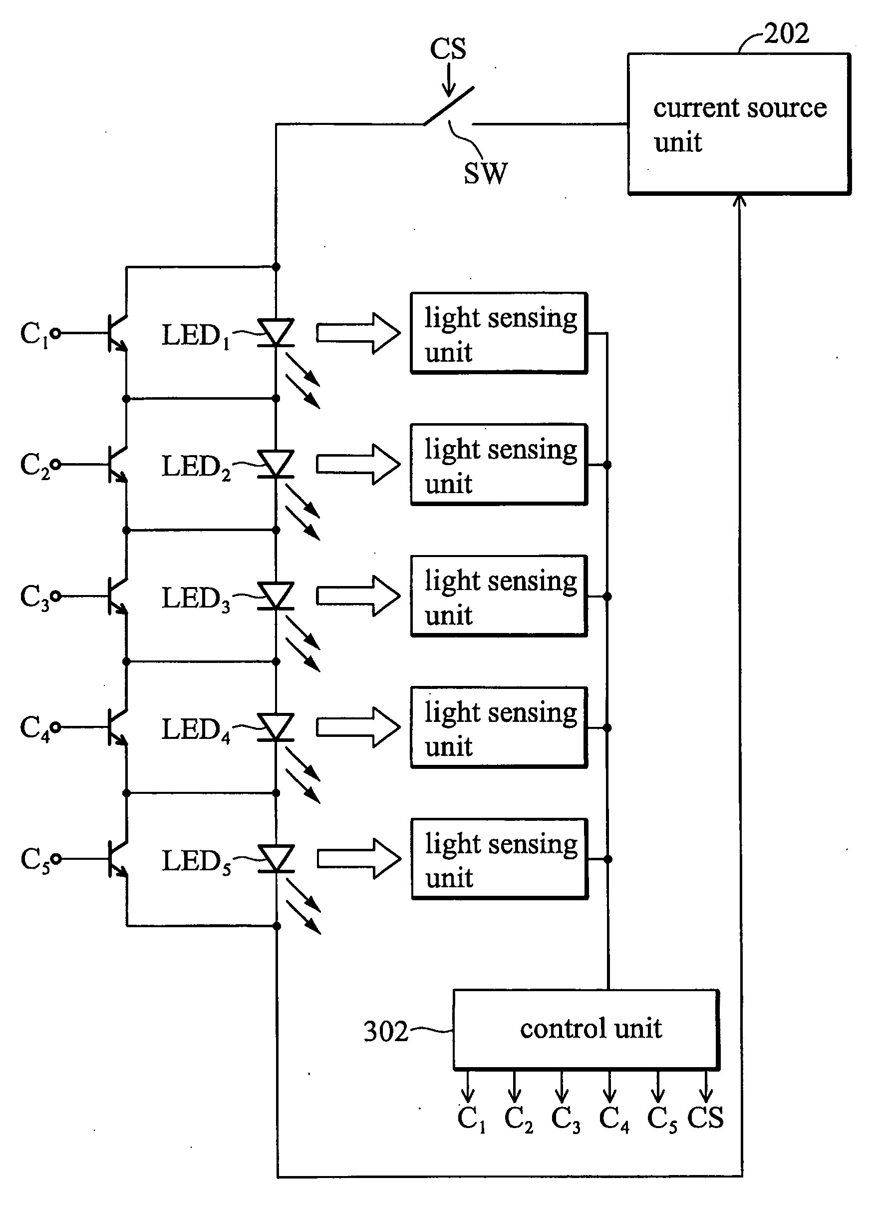
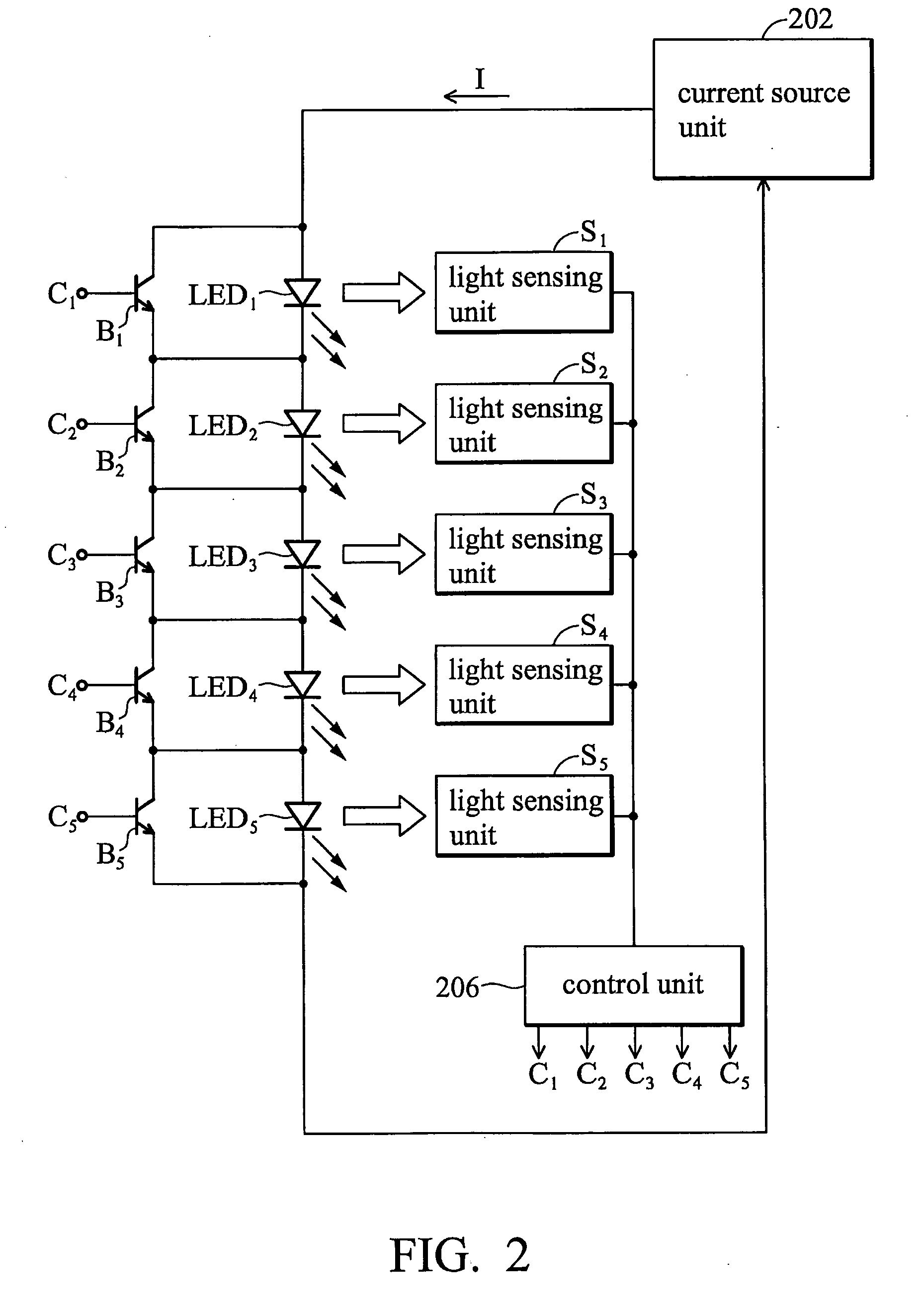
[0017]FIG. 2 illustrates an embodiment of the light source device of the invention. The light source device is applied in backlight modules of image display panels, and includes a current source unit 202, a plurality of light emitting units LED1-LED5, a plurality of current shunts B1-B5, a plurality of light sensing...


PUM


Abstract

The invention discloses light source devices applied in backlight modules of image display panels. The light source device includes a current source unit generating a driving current, a plurality of light emitting units coupled in series to the current source unit, a plurality of current shunts corresponding to the light emitting units respectively and providing current bypasses for the driving current to bypass the corresponding light emitting units, a plurality of light sensing units sensing the brightness of the light emitting units, and a control unit generating a plurality of current shunt control signals for separately controlling the current shunts. Each of the current shunt control signals is generated according to the sensed brightness of the corresponding light emitting unit and is used in controlling the conduction statement of the current bypass provided by the corresponding current shunt.

Description

BACKGROUND OF THE INVENTION[0001]1. Field of the Invention[0002]The present invention relates to light source devices and particularly relates to light source devices applied in backlight modules.[0003]2. Description of the Related Art[0004]The backlight module adopted in liquid crystal display (LCD) normally comprises a light source device implemented by a light emitting element array. The light emitting element array is composed of a plurality of light emitting elements. FIG. 1 illustrates a conventional light emitting element array. In this case, it is a 4×4 light emitting elements array. Each column of the light emitting element array includes a plurality of light emitting elements (LEDs) coupled in series. The LEDs of the same column share a single driving current I.[0005]The drawback of the conventional light emitting element array shown in FIG. 1 is that the brightness of each of the LEDs cannot be controlled separately. Referring to FIG. 1, the LEDs of the same column share ...

Claims


Application Information

Patent Timeline
IPC IPC(8): G01J1/32H01L33/00H05B37/02
CPCG01J1/32G09G3/3413G09G3/342G09G3/3426G09G2320/0233G09G2320/064Y02B20/347G09G2360/145G09G2360/16H05B33/0815H05B33/083H05B33/0869G09G2320/066H05B45/12H05B45/22H05B45/48H05B45/54Y02B20/30
Inventor LIU, CHAO-WENLIU, YUNG-LUNG
Owner CORETRONIC
Why Eureka
Eureka Blog
Learn More