Temperature detecting semiconductor device
a technology of semiconductor devices and temperature detection, applied in the direction of heat measurement, optical radiation measurement, instruments, etc., can solve the problems of insufficient temperature detection precision that cannot be provided in the conventional temperature detection circuit, and the inability to completely prevent the operation of erroneous devices due to temperature variation, etc., to achieve high precision
- Summary
- Abstract
- Description
- Claims
- Application Information
AI Technical Summary
Benefits of technology
Problems solved by technology
Method used
Image
Examples
first embodiment
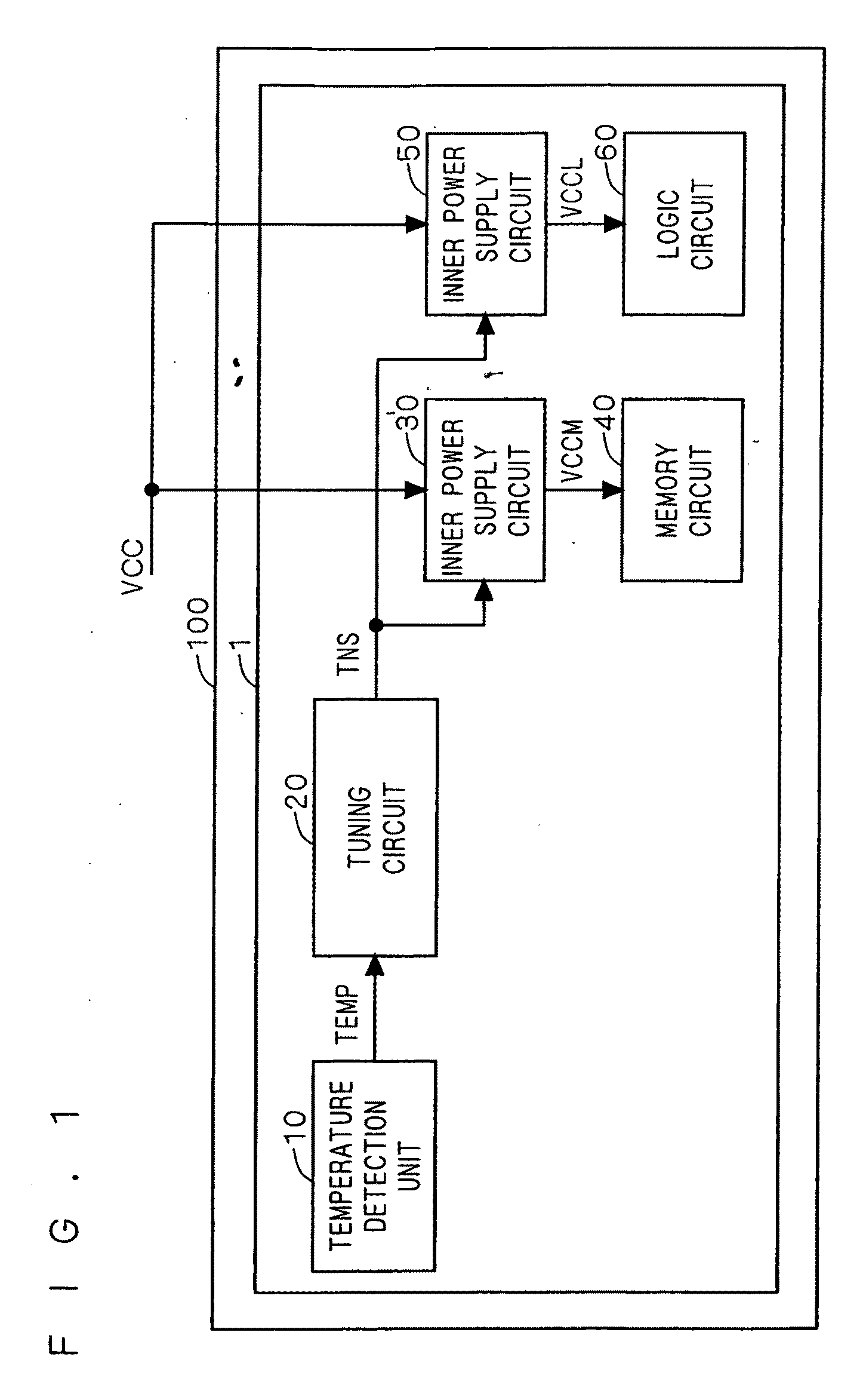
[0035]FIG. 1 is a block diagram showing a constitution of a semiconductor device according to a first embodiment of the present invention. As shown in FIG. 1, the semiconductor device according to the first embodiment includes a temperature detection unit 10, a tuning circuit 20, an inner power supply circuits 30 and 50, a memory circuit 40, and a logic circuit 60. These components are formed on a single semiconductor substrate 1 and the semiconductor substrate 1 is housed in a resin package 100.
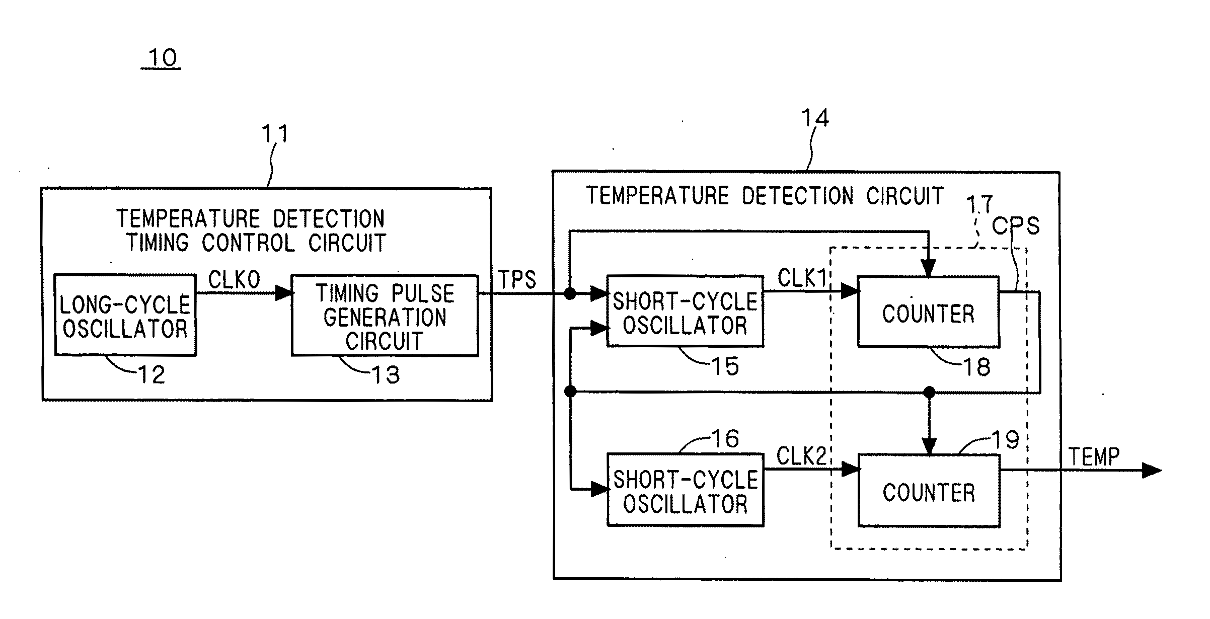
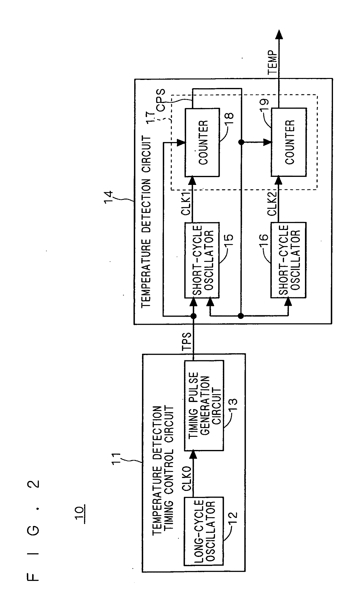
[0036]The temperature detection unit 10 detects a temperature T of the semiconductor device, and outputs its result as a temperature signal TEMP. The tuning circuit 20 generates an adjustment signal TNS based on the temperature signal TEMP outputted from the temperature detection unit 10 and supplies the adjustment signal TNS to the inner power supply circuits 30 and 50 so as to adjust their characteristics.
[0037]The inner power supply circuit 30 is a step-down power supply circuit, for exam...
second embodiment
[0085]Although the number of pulses of the clock signal CLK2 counted while the clock signal CLK1 is counted by N is outputted as the temperature signal TEMP in the semiconductor device according to the first embodiment, the number of pulses of the clock signals CLK1 and CLK2 may be counted for a predetermined period of time and a difference between the counted numbers may be outputted as the temperature signal TEMP. A description will be made of a detection circuit of a temperature T in this case hereinafter.
[0086]FIG. 13 is a block diagram showing a constitution of a temperature detection circuit 74 according to a second embodiment of the present invention. The temperature detection circuit 74 according to the second embodiment is used instead of the temperature detection circuit 14 in the semiconductor device according to the first embodiment.
[0087]As shown in FIG. 13, the temperature detection circuit 74 includes the above-described short-cycle oscillators 15 and 16 and a tempera...
third embodiment
[0096]Although the inner power supply circuits 30 and 50 are provided as the circuits whose characteristics are adjusted by the tuning circuit 20 in the first embodiment, the characteristics of the circuit other than the inner power supply circuits 30 and 50 can be adjusted by using the temperature signal TEMP of the present invention. According to a third embodiment, an example of the circuit other than the circuit to be adjusted will be described.
[0097]FIG. 15 is a block diagram showing a constitution of a timing generation circuit 90 whose electrical characteristics can be adjusted according to the temperature T by the above temperature detection circuit 10 and the tuning circuit 20. In an asynchronous circuit such as a DRAM, a plurality of timing pulse signals having different rising timings from each other are needed in general. The timing generation circuit 90 generates a plurality of timing pulse signals TPS1 to TPS5 to be supplied to the asynchronous circuit. For example, th...
PUM
| Property | Measurement | Unit |
|---|---|---|
| temperature | aaaaa | aaaaa |
| frequency | aaaaa | aaaaa |
| temperature characteristics | aaaaa | aaaaa |
Abstract
Description
Claims
Application Information
 - R&D
- Intellectual Property
- Life Sciences
- Materials
- Tech Scout
- Unparalleled Data Quality
- Higher Quality Content
- 60% Fewer Hallucinations
Browse by: Latest US Patents, China's latest patents, Technical Efficacy Thesaurus, Application Domain, Technology Topic, Popular Technical Reports.
© 2025 PatSnap. All rights reserved.Legal|Privacy policy|Modern Slavery Act Transparency Statement|Sitemap|About US| Contact US: help@patsnap.com


