Illumination device and projection system having the same

a technology of illumination device and projection system, which is applied in the field of optical systems, can solve the problems of increasing the size affecting the efficiency of the illumination system, so as to reduce the complexity of the manufacturing process, reduce the size and/or weight, and achieve high optical efficiency

Inactive Publication Date: 2009-03-05
SAMSUNG ELECTRONICS CO LTD
View PDF5 Cites 41 Cited by
  • Summary
  • Abstract
  • Description
  • Claims
  • Application Information

AI Technical Summary

Benefits of technology

[0009]The present invention provides an illumination device having a reduced size and / or weight. The complexity of a manufacturing process is also reduced and a high optical efficiency is realized.

Problems solved by technology

Because such conventional projection illuminating device includes the cube-shaped dichroic prism 4, its weight is large and a manufacturing cost is high.
Also, many optical components are needed to maintain a high optical efficiency, which increases the size of the illumination system.

Method used


Image

  • Illumination device and projection system having the same
  • Illumination device and projection system having the same
  • Illumination device and projection system having the same

Examples


Embodiment Construction

[0026]The present invention will now be described more fully with reference to the accompanying drawings, in which exemplary embodiments of the invention are shown. In the drawings, like reference numerals denote like elements, and the size of each element may be exaggerated for clarity and convenience.

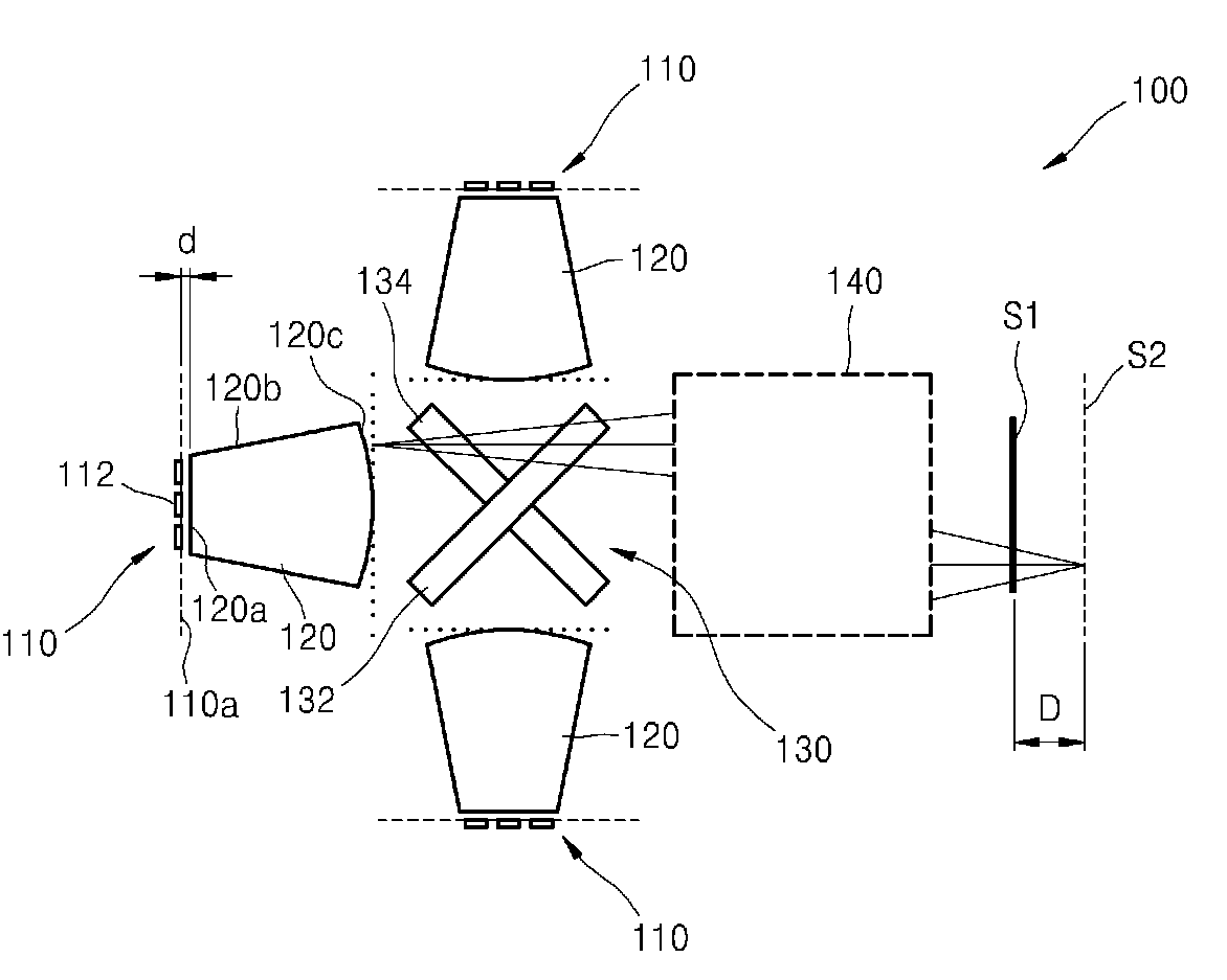
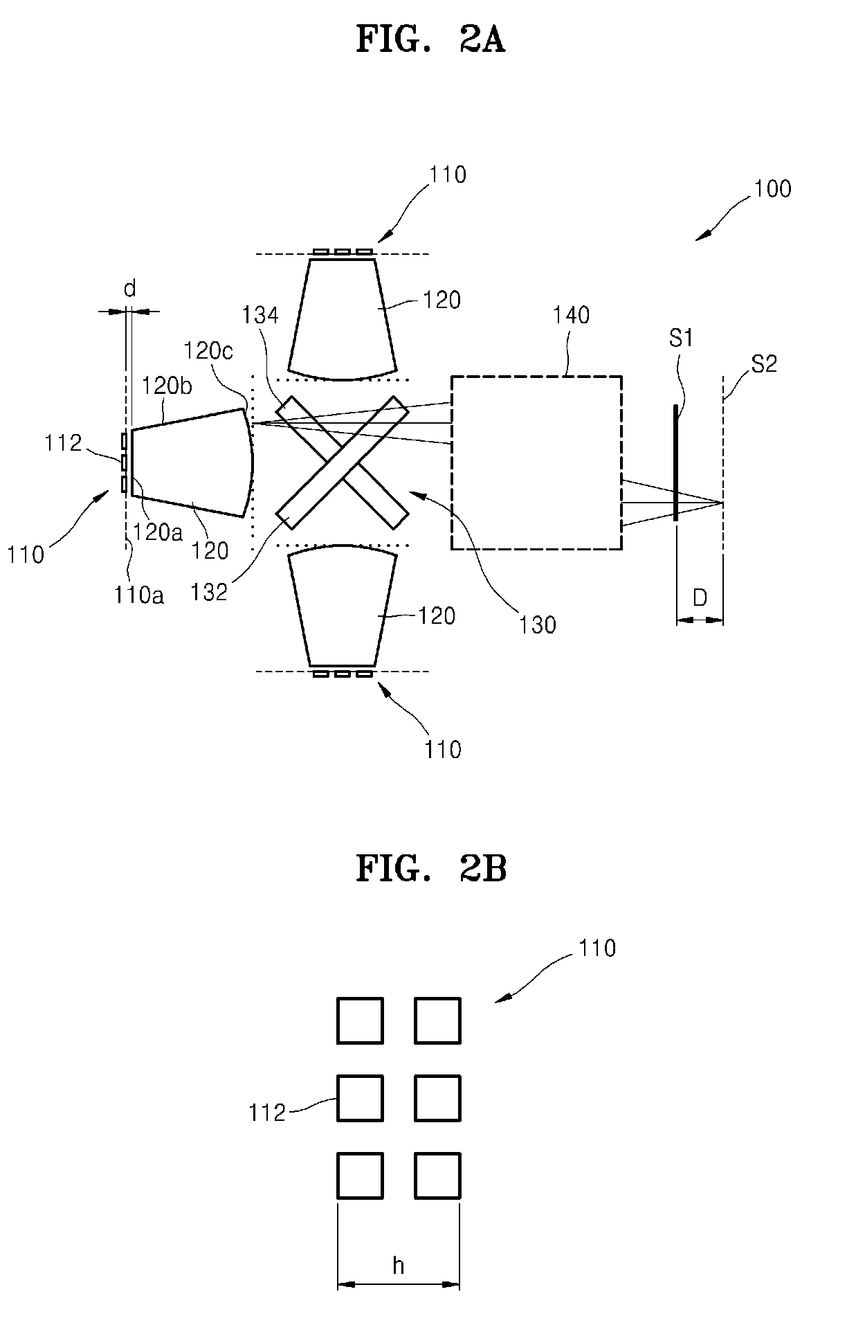
[0027]FIG. 2A schematically illustrates an illumination device 100 according to an exemplary embodiment of the present invention, and FIGS. 2B and 2C illustrate a minimal aperture of each of a plurality of light source units 110 and an illuminated surface S1 illustrated in FIG. 2A.

[0028]Referring to FIGS. 2A through 2C, the illumination device 100 according to an exemplary embodiment of the present invention is used to illuminate light on the illuminated surface S1. The illumination device 100 includes a plurality of light source units 110, a plurality of optical concentrators 120 respectively facing the light source units 110, a color synthesizing unit 130 synthesizing light emitted ...


PUM


Abstract

The illumination device includes a plurality of light source units and a plurality of optical concentrators facing the plurality of light source units and each having an entry surface, lateral surfaces, and an output surface. A color synthesizing unit synthesizes light emitted by the plurality of optical concentrators and includes two intersecting dichroic filters. A relay optical system transmits light synthesized by the color synthesizing unit to an illuminated surface.

Description

CROSS-REFERENCE TO RELATED PATENT APPLICATIONS[0001]This application claims priority from the Russian Patent Application No. RU2007133301, filed Sep. 5, 2007, in the Russian Patent Office, and the Korean Patent Application No. 10-2008-0044014, filed May 13, 2008 in the Korean Intellectual Property Office, the disclosures of which are incorporated herein in their entireties by reference.BACKGROUND OF THE INVENTION[0002]1. Field of the Invention[0003]The present invention relates to an optical system, and more particularly, to an illumination device which can be used in various projection systems such as projectors or projection televisions (TV).[0004]2. Description of the Related Art[0005]At present, illumination systems based on color light emitting diodes (LED) are widely used. Generally, the combination of red, green, and blue light is used in illumination systems in which an optical concentrator and optical tools for synthesizing light from LED groups are used.[0006]FIG. 1 illust...

Claims


Application Information

Patent Timeline
Patent Type & Authority Applications(United States)
IPC IPC(8): H04N9/31F21V8/00
CPCH04N9/3111H04N9/3197H04N9/3164
Inventor LINKOV, ALEXANDER EVGENIEVICHURUSOVA, MARIA VALERIEVNASERGIEVSKAYA, IRINA VLADIMIROVNABRATISHCHEV, ALEXEY VLADIMIROVICH
Owner SAMSUNG ELECTRONICS CO LTD
Why Eureka
Try Eureka