Optical film, and glass

a technology of optical film and glass, applied in the field of optical film, can solve the problems of ineffective strong unwanted reflections, and inability to achieve sufficient prevention of unwanted reflections obliquely in front of the windshield and side window glasses, etc., to achieve excellent prevention of unwanted reflections, improve the anti-reflection effect of an interior surface, and flexible design

Inactive Publication Date: 2009-03-05
FUJIFILM CORP
View PDF0 Cites 31 Cited by
  • Summary
  • Abstract
  • Description
  • Claims
  • Application Information

AI Technical Summary

Benefits of technology

[0009]The present invention aims to provide an optical film having excellent prevention of unwanted reflections in wide areas including a whole area of a windshield and side window glasses in various kinds of vehicles, outstandingly improved antireflection effect of an interior s

Problems solved by technology

However, a horizontal polarizer used alone can be effective to obtain sufficient prevention of unwanted reflections in the region of the windshield right in front of the driver, but not effective to obtain sufficient prevention of unwanted reflections obliquely in front of the windshield and side window glasses.
The market research of automobile manufacturers reveals that the problem of unwanted reflections occurs not only in the windshield but also in side window glasses of the driver seat.
Moreover, passengers switch on interior lights at night, and e

Method used


Image

  • Optical film, and glass
  • Optical film, and glass
  • Optical film, and glass

Examples


example 1

Production of Optical Film

—Preparation of Vertically Polarizing Film—

[0244]To a liquid crystal solution prepared by dissolving 3.04 g of a liquid crystal compound having a photo-polymerizable group (PALIOCOLOR LC242, manufactured by BASF) and 0.1 g of a polymer surfactant (MEGAFAC F780F by Dainippon Ink and Chemicals, Inc.) in 5.07 g of methyl ethyl ketone (MEK), 1.11 g of an initiator solution prepared by dissolving 0.90 g of IRGACURE 907 (manufactured by Chiba Specialty Chemicals K.K.) and 0.30 g of KAYACURE DETX (manufactured by Nippon Kayaku Co., Ltd.) in 8.80 g of methyl ethyl ketone (MEK), was added and stirred for 5 minutes to be fully dissolved, thereby obtaining a coating solution for vertically polarizing film.

[0245]Next, onto a surface of a 100 mm×100 mm triacetyl cellulose (TAC) film (TD80U by FUJIFILM CORPORATION) where a PVA orientation film was to be deposited, 10 mass % aqueous solution of polyvinyl alcohol (MP203 by Kuraray Co., Ltd.) was applied by spin coating at ...

example 2

Production of Optical Film

[0253]An optical film of Example 2 was produced in the same manner as in Example 1, except that 5 mass % of HAuCl4.3H2O (by Kanto Chemical Co., Inc) in a methyl ethyl ketone solution in the vertically polarizing film of Example 1 was replaced with 5 mass % of AgNO3 (by Kanto Chemical Co., Inc) in a dimethylacetamide solution.

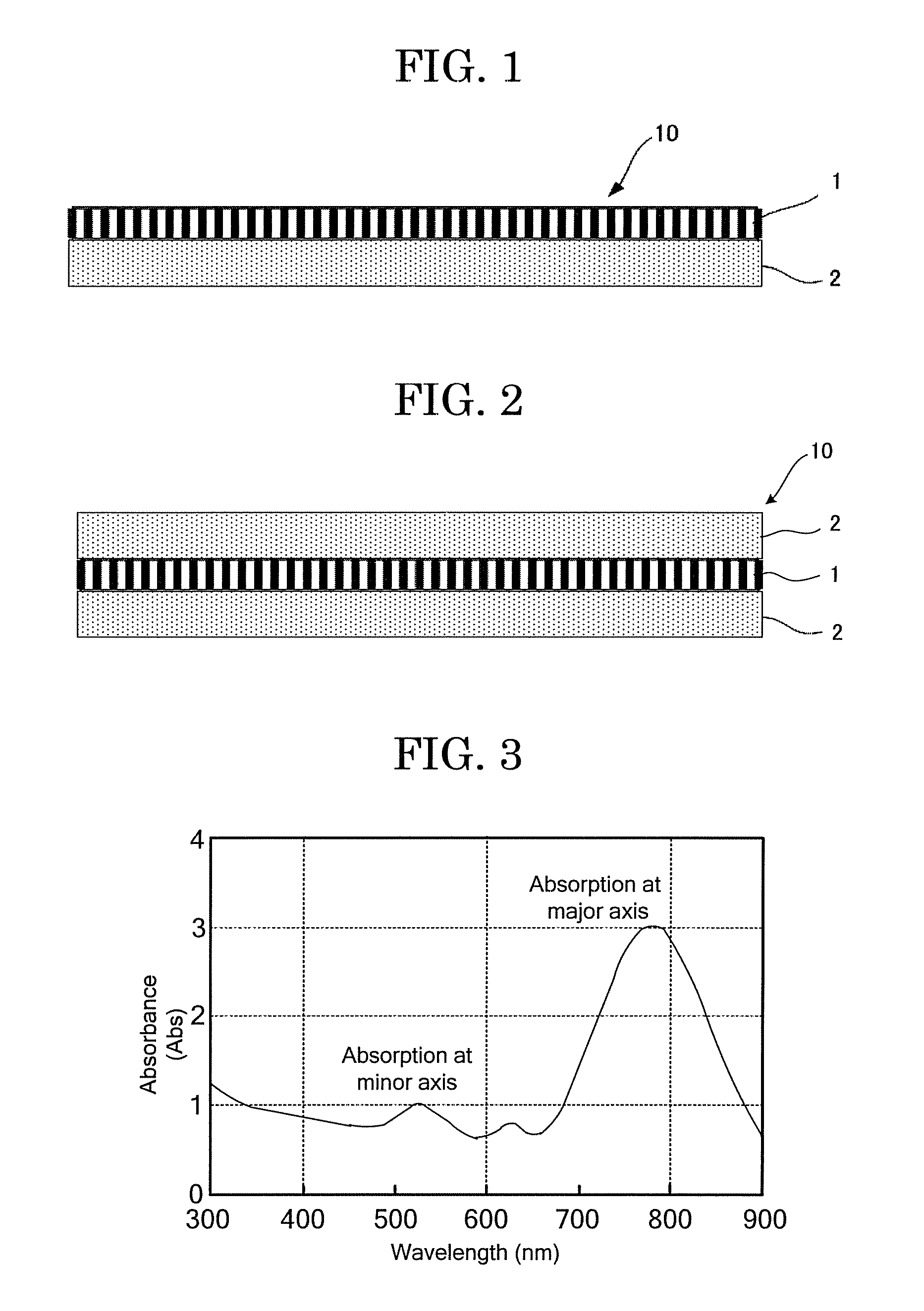
[0254]When a section of the obtained vertically polarizing film, which was a part of the optical film of Example 2 was observed using a transmission electron microscope (TEM) (JEM-2010 by JEOL Ltd.), Ag nanorods were substantially vertically oriented relative to a base surface. The Ag nanorods had an average aspect ratio (major axis length / minor axis length) of 2.8.

example 3

Production of Optical Film

[0255]An optical film of Example 3 was produced in the same manner as in Example 1, except that the liquid crystal compound in the vertically polarizing film in Example 1 was change from LC242 to RM257 (by Merk Ltd.).

[0256]When a section of the obtained vertically polarizing film, which was a part of the optical film of Example 3 was observed using a transmission electron microscope (TEM) (JEM-2010 by JEOL Ltd.), Au nanorods were substantially vertically oriented relative to a base surface. The Au nanorods had an average aspect ratio (major axis length / minor axis length) of 2.7.


PUM

PropertyMeasurementUnit
Angleaaaaaaaaaa
Angleaaaaaaaaaa

Abstract

The present invention provides glass containing a base, and an optical film, wherein the optical film contains a vertically polarizing film having a polarizer whose absorption axis is substantially vertically oriented to a film surface, and a π/2 optical rotation film containing an optical rotator for rotating a vibration direction of linearly polarized light by substantially 90 degrees.

Description

BACKGROUND OF THE INVENTION[0001]1. Field of the Invention[0002]The present invention relates to an optical film suitably used for windshields and side window glasses of all kinds of vehicles, and also relates to glass using the optical film.[0003]2. Description of the Related Art[0004]As a method for suppressing unwanted reflections (specifically, surrounding views reflected on glass) of an image on the front window (windshield) of a vehicle from the dashboard inside the vehicle, the inventor of the present invention has proposed a method in which a polarizing film containing a horizontal polarizer which absorbs S wave is used for a windshield of a vehicle so as to absorb the S wave of reflected light, thereby suppressing unwanted reflections on glass (Japanese Patent Application Laid-Open (JP-A) No. 2007-334150).[0005]The inclination angle of windshields used in common private cars has been approximately 30 degrees in order to reduce air resistance for about 20 years. Thus, an ima...

Claims


Application Information

Patent Timeline
IPC IPC(8): G02B5/30G02B1/08
CPCB32B17/10B32B17/10036B32B17/10174B32B17/10761B60J3/007B60J3/06G02B2207/101B82Y20/00B82Y30/00G02B5/3058B32B2317/18B32B17/10458G02B5/30
Inventor KAMADA, KOH
Owner FUJIFILM CORP
Why Eureka
Try Eureka